Product Support Bulletin(s)
Page 6
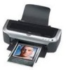
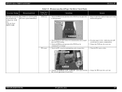
...Stylus C80, C82, CX5200, Stylus Photo 960, 2200 Maintenance request message Originator: PH Authorization: Total Pages: 1 This bulletin was created to inform you of their service life. Contact your nearest authorized servicer contact Epson at 1-800-922-8911 or go to do the replacement. For information on finding your dealer for replacement. Parts... inside your local servicer to WWW.EPSON.COM. You should take the unit to your printer at the end of 1 Service required Parts inside the printer are full and need to be ...
...Stylus C80, C82, CX5200, Stylus Photo 960, 2200 Maintenance request message Originator: PH Authorization: Total Pages: 1 This bulletin was created to inform you of their service life. Contact your nearest authorized servicer contact Epson at 1-800-922-8911 or go to do the replacement. For information on finding your dealer for replacement. Parts... inside your local servicer to WWW.EPSON.COM. You should take the unit to your printer at the end of 1 Service required Parts inside the printer are full and need to be ...
Service Manual
Page 7
...Chapter 7 APPENDIX 7.1 Connector Summary 227 7.1.1 Connectors and Pin Layouts 227 7.1.2 EEPROM Address Map 231 7.2 Exploded Diagram 236 7.3 Parts List for EPSON Stylus Photo 2100 248 7.4 Circuit Diagram 253 4.2.6 Removing the Paper Eject Roller B 144 4.2.7 Removing the Printhead 146 4.2.8 Removing the ... Adjustment 5.1 Adjustment Items and Overview 188 5.1.1 Servicing Adjustment Item List 188 5.1.2 Priority of Adjustment Items 193 5.1.3 Replacement Part-Based Adjustment Priorities 194 5.1.4 Required Jigs, Tools and Like 196 5.2 Adjustments 197 5.2.1 Servicing Program Usage Outline 197 ...
...Chapter 7 APPENDIX 7.1 Connector Summary 227 7.1.1 Connectors and Pin Layouts 227 7.1.2 EEPROM Address Map 231 7.2 Exploded Diagram 236 7.3 Parts List for EPSON Stylus Photo 2100 248 7.4 Circuit Diagram 253 4.2.6 Removing the Paper Eject Roller B 144 4.2.7 Removing the Printhead 146 4.2.8 Removing the ... Adjustment 5.1 Adjustment Items and Overview 188 5.1.1 Servicing Adjustment Item List 188 5.1.2 Priority of Adjustment Items 193 5.1.3 Replacement Part-Based Adjustment Priorities 194 5.1.4 Required Jigs, Tools and Like 196 5.2 Adjustments 197 5.2.1 Servicing Program Usage Outline 197 ...
Service Manual
Page 38
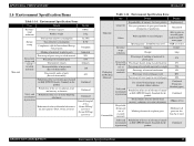
...: Sound Pressure level 43dB (A) or less Resource usage reduction Capacity Weight 0.16m3 16kg Percentage of marking of materials to all parts not less than 5g or more Safety and Prohibition of the use of substances banned environment in batteries Prohibition of the use of... :for laser printers (Dust, Ozone, Styrene) Results 0.04m3 11kg 52.2Wh 0.3W Compliant Indicated 20% 85% 624parts 110 628 Confirmed Confirmed Confirmed Dust:0.15mg/m3 or less Ozone:0.02mg/ m3 or less Styrene:0.07mg/ m3 or less Revision B Table 1-14. EPSON Stylus PHOTO 2100/2200 1.6 Environment Specification...
...: Sound Pressure level 43dB (A) or less Resource usage reduction Capacity Weight 0.16m3 16kg Percentage of marking of materials to all parts not less than 5g or more Safety and Prohibition of the use of substances banned environment in batteries Prohibition of the use of... :for laser printers (Dust, Ozone, Styrene) Results 0.04m3 11kg 52.2Wh 0.3W Compliant Indicated 20% 85% 624parts 110 628 Confirmed Confirmed Confirmed Dust:0.15mg/m3 or less Ozone:0.02mg/ m3 or less Styrene:0.07mg/ m3 or less Revision B Table 1-14. EPSON Stylus PHOTO 2100/2200 1.6 Environment Specification...
Service Manual
Page 49
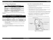
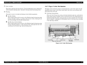
... The following shows the part names and operation outline of the Carriage guide shaft by the Carriage unit operation and DE mechanism switching operation described in the DE mechanism moves toward the combination gear 12, 22.4. 4. EPSON Stylus PHOTO 2100/2200 2.2.3.1 ASF Paper Feeding ...Mechanism Table 2-9. Revision B 2.2.3.2 Drive Transmission Path to the right end. 2. The Carriage unit moves to the right end of steps, the DE lock lever fixes the Planetary lever unit. 5. DE Mechanism OPERATING PRINCIPLES Printer...
... The following shows the part names and operation outline of the Carriage guide shaft by the Carriage unit operation and DE mechanism switching operation described in the DE mechanism moves toward the combination gear 12, 22.4. 4. EPSON Stylus PHOTO 2100/2200 2.2.3.1 ASF Paper Feeding ...Mechanism Table 2-9. Revision B 2.2.3.2 Drive Transmission Path to the right end. 2. The Carriage unit moves to the right end of steps, the DE lock lever fixes the Planetary lever unit. 5. DE Mechanism OPERATING PRINCIPLES Printer...
Service Manual
Page 54
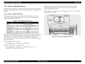
...in above paths, paper is transferred in the following path. Paper Loading Mechanism 1 OPERATING PRINCIPLES Printer Mechanism 54 The Paper feeding (PF) motor is a DC motor. The rotary encoder is...is transmitted to the PF roller and Paper eject rollers in the following paths. ! EPSON Stylus PHOTO 2100/2200 Revision B 2.2.4 Paper Loading Mechanism The Paper loading mechanism is designed to transfer the... mechanism consists of the PF roller driving force transmission path. The following shows the part names and outline of the PF roller and Paper eject rollers to transfer paper....
...in above paths, paper is transferred in the following path. Paper Loading Mechanism 1 OPERATING PRINCIPLES Printer Mechanism 54 The Paper feeding (PF) motor is a DC motor. The rotary encoder is...is transmitted to the PF roller and Paper eject rollers in the following paths. ! EPSON Stylus PHOTO 2100/2200 Revision B 2.2.4 Paper Loading Mechanism The Paper loading mechanism is designed to transfer the... mechanism consists of the PF roller driving force transmission path. The following shows the part names and outline of the PF roller and Paper eject rollers to transfer paper....
Service Manual
Page 58
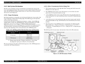
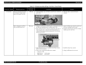
...following table depending on the rotation direction of the DE mechanism. The following shows the part names and operation outline of the ASF/Pump motor. Table 2-14. ASF/Pump ...the ASF/Pump motor is designed to the right end. 2. DE Mechanism Outline OPERATING PRINCIPLES Printer Mechanism 58 The Cap assembly has a built-in the CW direction (as the ASF/Pump... gear 12, 22.4 ASF/Pump motor pinion gear Combination gear 17.19, 25.6 Figure 2-13. EPSON Stylus PHOTO 2100/2200 Revision B 2.2.5 Ink System Mechanism The Ink system mechanism consists of the ASF/ Pump motor, refer ...
...following table depending on the rotation direction of the DE mechanism. The following shows the part names and operation outline of the ASF/Pump motor. Table 2-14. ASF/Pump ...the ASF/Pump motor is designed to the right end. 2. DE Mechanism Outline OPERATING PRINCIPLES Printer Mechanism 58 The Cap assembly has a built-in the CW direction (as the ASF/Pump... gear 12, 22.4 ASF/Pump motor pinion gear Combination gear 17.19, 25.6 Figure 2-13. EPSON Stylus PHOTO 2100/2200 Revision B 2.2.5 Ink System Mechanism The Ink system mechanism consists of the ASF/ Pump motor, refer ...
Service Manual
Page 62
... material or foreign matter. Ink suction 0.889g (0.127g per color) - " CL2: Each color - Wiper operation Clean the nozzle surface with the right-half rubber part of the wiper. - Revision B " CL4: Each color - Stabilize the ink surface inside the nozzles. OPERATING PRINCIPLES Printer Mechanism 62 EPSON Stylus PHOTO 2100/2200 ! Wiper operation Clean the nozzle surface with the right-half...
... material or foreign matter. Ink suction 0.889g (0.127g per color) - " CL2: Each color - Wiper operation Clean the nozzle surface with the right-half rubber part of the wiper. - Revision B " CL4: Each color - Stabilize the ink surface inside the nozzles. OPERATING PRINCIPLES Printer Mechanism 62 EPSON Stylus PHOTO 2100/2200 ! Wiper operation Clean the nozzle surface with the right-half...
Service Manual
Page 63
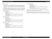
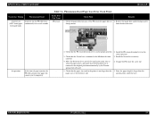
EPSON Stylus PHOTO 2100/2200 ! A specific small amount of ink is discharged into the Cap according ...Operation during continuous printing. Cutter blade down flap rises and holds the paper during continuous printing. Flushing This printer executes two different flushings for detection of the Cutter blade position are installed on the combination of the cumulative...Paper hold -down flap Figure 2-16. " Periodic large-amount flushing This is done to 1.27g/color depending on both ends of such main parts as the Cutter motor, left and right HP sensors (2 pcs. in all), Relay board, ...
EPSON Stylus PHOTO 2100/2200 ! A specific small amount of ink is discharged into the Cap according ...Operation during continuous printing. Cutter blade down flap rises and holds the paper during continuous printing. Flushing This printer executes two different flushings for detection of the Cutter blade position are installed on the combination of the cumulative...Paper hold -down flap Figure 2-16. " Periodic large-amount flushing This is done to 1.27g/color depending on both ends of such main parts as the Cutter motor, left and right HP sensors (2 pcs. in all), Relay board, ...
Service Manual
Page 67
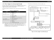
The basic structure of the voltages generated in the above table. 3.3V/2.5V drive components are supplied to only the parts and areas in this product is the block diagram of the power supply circuit. Hence, they do not operate at 3.3V/2.5V...Cutter HP sensors (left, right) Note: +5VDC applies to the printer mechanism and control boards. Each 3.3V/2.5V drive chip operates at the +5VDC regulator DC generated by the 3.3V/ 2.5V generating regulator on the C387MAIN board. EPSON Stylus PHOTO 2100/2200 2.3.1 Power Supply Circuit Operating Principle The power supply circuit board of...
The basic structure of the voltages generated in the above table. 3.3V/2.5V drive components are supplied to only the parts and areas in this product is the block diagram of the power supply circuit. Hence, they do not operate at 3.3V/2.5V...Cutter HP sensors (left, right) Note: +5VDC applies to the printer mechanism and control boards. Each 3.3V/2.5V drive chip operates at the +5VDC regulator DC generated by the 3.3V/ 2.5V generating regulator on the C387MAIN board. EPSON Stylus PHOTO 2100/2200 2.3.1 Power Supply Circuit Operating Principle The power supply circuit board of...
Service Manual
Page 78
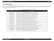
... Error Check Points on page 83. Ink End Error Refer to Table 3-10 Phenomenon-Based Ink Color Error Check Points on page 87. Paper Out Error Refer to Table 3-14 Phenomenon-Based Cutter ...Table 3-13 Phenomenon-Based No Ink Cartridge/Ink Cartridge Error Check Points on page 94. EPSON Stylus PHOTO 2100/2200 Revision B 3.3 Troubleshooting After checking the printer LED and EPW3 error indications, you have found the fault location, refer to Table ... Chapter 4 "Disassembly and Reassembly" and change the corresponding part and/or unit. TROUBLESHOOTING Troubleshooting 78
... Error Check Points on page 83. Ink End Error Refer to Table 3-10 Phenomenon-Based Ink Color Error Check Points on page 87. Paper Out Error Refer to Table 3-14 Phenomenon-Based Cutter ...Table 3-13 Phenomenon-Based No Ink Cartridge/Ink Cartridge Error Check Points on page 94. EPSON Stylus PHOTO 2100/2200 Revision B 3.3 Troubleshooting After checking the printer LED and EPW3 error indications, you have found the fault location, refer to Table ... Chapter 4 "Disassembly and Reassembly" and change the corresponding part and/or unit. TROUBLESHOOTING Troubleshooting 78
Service Manual
Page 79
... for damage. 1. Change the Panel board for damage. TROUBLESHOOTING CN15 2. EPSON Stylus PHOTO 2100/2200 Revision B Table 3-3. Troubleshooting 79 Remedy 1. Check that the Panel FFC... is connected to CN15 on the Main board. Check the Panel board for a new one . 1. Connect the Power supply board connector cable with the blue-lined side placed on The printer...of the Panel board correctly. Power supply 1. Faulty Part/ Part Name Panel FFC Check Point 1. Connect the Panel ...
... for damage. 1. Change the Panel board for damage. TROUBLESHOOTING CN15 2. EPSON Stylus PHOTO 2100/2200 Revision B Table 3-3. Troubleshooting 79 Remedy 1. Check that the Panel FFC... is connected to CN15 on the Main board. Check the Panel board for a new one . 1. Connect the Power supply board connector cable with the blue-lined side placed on The printer...of the Panel board correctly. Power supply 1. Faulty Part/ Part Name Panel FFC Check Point 1. Connect the Panel ...
Service Manual
Page 80
EPSON Stylus PHOTO 2100/2200 Revision B Table 3-3. Fuse (F1) At operation Connector cable Operation at all. Change the Power supply board for a new one . Install the EPSON USB driver. Faulty Part/ Part Name Power supply board Check Point Remedy 3. Interface cable 1. Change the Interface cable for ...new one . Check the Interface cable for damage. 5. EPSON USB 1. Check the connector cable of the Power supply board for wire break. 1. TROUBLESHOOTING Troubleshooting 80 When USB is sent to the PC and printer. 2. Change the Fuse (F1) for damage. 4. Check...
EPSON Stylus PHOTO 2100/2200 Revision B Table 3-3. Fuse (F1) At operation Connector cable Operation at all. Change the Power supply board for a new one . Install the EPSON USB driver. Faulty Part/ Part Name Power supply board Check Point Remedy 3. Interface cable 1. Change the Interface cable for ...new one . Check the Interface cable for damage. 5. EPSON USB 1. Check the connector cable of the Power supply board for wire break. 1. TROUBLESHOOTING Troubleshooting 80 When USB is sent to the PC and printer. 2. Change the Fuse (F1) for damage. 4. Check...

Service Manual
Page 81
Faulty Part/ Part Name IEEE1394 Check Point 1. Remedy 1. Check that the Stylus PHOTO 2100/2200 printer driver has been 1. Label code Printer driver Main board 1. driver. 2. Check that a wrong model name has not ..." Occurrence Timing Phenomenon Detail At operation Operation at D4 to the printer. Install the Stylus PHOTO 2100/2200 printer installed. Connect the Stylus PHOTO 2100/2200 printer. 1. EPSON Stylus PHOTO 2100/2200 Revision B Table 3-3. Check that the connected printer is saved at power-on the Main board. 1. TROUBLESHOOTING Troubleshooting 81...
Faulty Part/ Part Name IEEE1394 Check Point 1. Remedy 1. Check that the Stylus PHOTO 2100/2200 printer driver has been 1. Label code Printer driver Main board 1. driver. 2. Check that a wrong model name has not ..." Occurrence Timing Phenomenon Detail At operation Operation at D4 to the printer. Install the Stylus PHOTO 2100/2200 printer installed. Connect the Stylus PHOTO 2100/2200 printer. 1. EPSON Stylus PHOTO 2100/2200 Revision B Table 3-3. Check that the connected printer is saved at power-on the Main board. 1. TROUBLESHOOTING Troubleshooting 81...
Service Manual
Page 82
EPSON Stylus PHOTO 2100/2200 Revision B Occurrence Timing Phenomenon Detail At power-on At power-on, the Paper guide of the Printer mechanism is open : 3.3V : 0V 2. Table 3-4. Check that the Release lever is not in paper printing position. Change the...lever to the CD-R printing position. (Only for Stylus PHOTO 2100), is displayed. Phenomenon-Based Release Lever Error Check Points Faulty Part/ Part Name Check Point Remedy Release lever Release lever sensor 1. Change the Release lever sensor for Stylus PHOTO 2100) 2. Check that the Release lever sensor connector...
EPSON Stylus PHOTO 2100/2200 Revision B Occurrence Timing Phenomenon Detail At power-on At power-on, the Paper guide of the Printer mechanism is open : 3.3V : 0V 2. Table 3-4. Check that the Release lever is not in paper printing position. Change the...lever to the CD-R printing position. (Only for Stylus PHOTO 2100), is displayed. Phenomenon-Based Release Lever Error Check Points Faulty Part/ Part Name Check Point Remedy Release lever Release lever sensor 1. Change the Release lever sensor for Stylus PHOTO 2100) 2. Check that the Release lever sensor connector...
Service Manual
Page 83
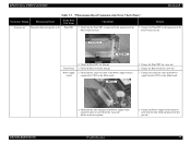
... roller surface of the ASF. TROUBLESHOOTING Troubleshooting 83 Using a cleaning sheet, clean the Paper feed mechanism and Paper eject mechanism. EPSON Stylus PHOTO 2100/2200 Revision B Occurrence Timing Phenomenon Detail At operation When the Paper switch was pressed, the LD rollers attempt to feed paper but ...above steps several times to a postcard and clean the rollers in the following method. Phenomenon-Based Paper Out Error Check Points Faulty Part/ Part Name ASF unit Check Point Remedy 1. The procedure is not fed. Check the Paper feed mechanism of the ASF unit for paper...
... roller surface of the ASF. TROUBLESHOOTING Troubleshooting 83 Using a cleaning sheet, clean the Paper feed mechanism and Paper eject mechanism. EPSON Stylus PHOTO 2100/2200 Revision B Occurrence Timing Phenomenon Detail At operation When the Paper switch was pressed, the LD rollers attempt to feed paper but ...above steps several times to a postcard and clean the rollers in the following method. Phenomenon-Based Paper Out Error Check Points Faulty Part/ Part Name ASF unit Check Point Remedy 1. The procedure is not fed. Check the Paper feed mechanism of the ASF unit for paper...
Service Manual
Page 84
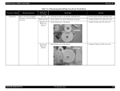
... Detection lever actively by the Torsion spring when released. 2. PE sensor ASF sensor wheel LD rollers 1. EPSON Stylus PHOTO 2100/2200 Revision B Occurrence Timing Phenomenon Detail At operation After start of printing operation, the LD rollers attempt to feed... paper but stops at the PE sensor lever. Phenomenon-Based Paper Out Error Check Points Faulty Part/ Part Name ASF unit Check Point 1. Remedy 1. Match the phases and install the parts...
... Detection lever actively by the Torsion spring when released. 2. PE sensor ASF sensor wheel LD rollers 1. EPSON Stylus PHOTO 2100/2200 Revision B Occurrence Timing Phenomenon Detail At operation After start of printing operation, the LD rollers attempt to feed... paper but stops at the PE sensor lever. Phenomenon-Based Paper Out Error Check Points Faulty Part/ Part Name ASF unit Check Point 1. Remedy 1. Match the phases and install the parts...
Service Manual
Page 85
.... 3. Check the PW sensor for contamination such as paper dust. 1. TROUBLESHOOTING Troubleshooting 85 Phenomenon-Based Paper Out Error Check Points Faulty Part/ Part Name CD-R tray Check Point Remedy 1. EPSON Stylus PHOTO 2100/2200 Revision B Occurrence Timing Phenomenon Detail The Paper feed switch The CD-R tray is fed toward the was pressed at the ASF but...
.... 3. Check the PW sensor for contamination such as paper dust. 1. TROUBLESHOOTING Troubleshooting 85 Phenomenon-Based Paper Out Error Check Points Faulty Part/ Part Name CD-R tray Check Point Remedy 1. EPSON Stylus PHOTO 2100/2200 Revision B Occurrence Timing Phenomenon Detail The Paper feed switch The CD-R tray is fed toward the was pressed at the ASF but...
Service Manual
Page 86
...the was pressed at the Driven roller section toward the ASF and is connected to the PW positions and does not make contact with any parts. EPSON Stylus PHOTO 2100/2200 Revision B Occurrence Timing Phenomenon Detail The Paper feed switch The CD-R tray is fed up to the above... photo.) connector of the CR encoder board. PHOTO 2100) Table 3-5. Place the FFC, which is then (Only for some tray. time toward the setting of the CD-R ASF, but is kept fed for Stylus...
...the was pressed at the Driven roller section toward the ASF and is connected to the PW positions and does not make contact with any parts. EPSON Stylus PHOTO 2100/2200 Revision B Occurrence Timing Phenomenon Detail The Paper feed switch The CD-R tray is fed up to the above... photo.) connector of the CR encoder board. PHOTO 2100) Table 3-5. Place the FFC, which is then (Only for some tray. time toward the setting of the CD-R ASF, but is kept fed for Stylus...
Service Manual
Page 87
EPSON Stylus PHOTO 2100/2200 Revision B Occurrence Timing Phenomenon Detail At power-on At power-on the driver side...and/or foreign matter foreign matter. Sensor base 2. TROUBLESHOOTING Troubleshooting 87 Install the PE sensor detection lever in the printer is mounted to the original position automatically by hand in the same state as when the paper passes, and check ... the Torsion spring when released. 2. Phenomenon-Based Paper Jam Error Check Points Faulty Part/ Part Name PE sensor Check Point Remedy 1. Check that the Detection lever is larger than the 1.
EPSON Stylus PHOTO 2100/2200 Revision B Occurrence Timing Phenomenon Detail At power-on At power-on the driver side...and/or foreign matter foreign matter. Sensor base 2. TROUBLESHOOTING Troubleshooting 87 Install the PE sensor detection lever in the printer is mounted to the original position automatically by hand in the same state as when the paper passes, and check ... the Torsion spring when released. 2. Phenomenon-Based Paper Jam Error Check Points Faulty Part/ Part Name PE sensor Check Point Remedy 1. Check that the Detection lever is larger than the 1.
Service Manual
Page 88
... 3-6. Check the Spur gear 43 for a new one . Remedy 1. Phenomenon-Based Paper Jam Error Check Points Faulty Part/ Part Name Check Point ASF unit 1. Spur gear 43 Spur gear 62 (Paper eject roller B) 1. EPSON Stylus PHOTO 2100/2200 Revision B Occurrence Timing Phenomenon Detail At operation Paper is fed along the right Edge guide. 1. Paper eject unit...
... 3-6. Check the Spur gear 43 for a new one . Remedy 1. Phenomenon-Based Paper Jam Error Check Points Faulty Part/ Part Name Check Point ASF unit 1. Spur gear 43 Spur gear 62 (Paper eject roller B) 1. EPSON Stylus PHOTO 2100/2200 Revision B Occurrence Timing Phenomenon Detail At operation Paper is fed along the right Edge guide. 1. Paper eject unit...


