
Service Manual
Page 27
EPSON Stylus PHOTO 2100/2200 FUNCTIONS AT POWER-ON Table 1-11. For details, refer to"Status Printing" on Page 30. 00h Firmware version, selected Code Page, Waste ink counter and nozzle test pattern are printed. 01h Hexadecimal dump mode *b : For details, refer to "Panel ...corresponding addresses of the EEPROM. Special Setting Mode *a Switch Function Paper switch EEPROM and Timer IC reset *b Roll paper switch (10 seconds) Waste ink counter reset *c *a : This operation resets the following data at the corresponding addresses of the EEPROM. • 26-27 Last cleaning time:...
EPSON Stylus PHOTO 2100/2200 FUNCTIONS AT POWER-ON Table 1-11. For details, refer to"Status Printing" on Page 30. 00h Firmware version, selected Code Page, Waste ink counter and nozzle test pattern are printed. 01h Hexadecimal dump mode *b : For details, refer to "Panel ...corresponding addresses of the EEPROM. Special Setting Mode *a Switch Function Paper switch EEPROM and Timer IC reset *b Roll paper switch (10 seconds) Waste ink counter reset *c *a : This operation resets the following data at the corresponding addresses of the EEPROM. • 26-27 Last cleaning time:...

Service Manual
Page 29
... Power and Paper LEDs blink 2 and all Ink LEDs are lit. EPSON Stylus PHOTO 2100/2200 1.3.6 Special Setting Mode Function EEPROM AND TIMER IC RESET By operating the panel at power-on , you can reset the EEPROM and Timer IC. Waste ink counter reset ends and the printer starts. *a : If the switch is not pressed within the time when...
... Power and Paper LEDs blink 2 and all Ink LEDs are lit. EPSON Stylus PHOTO 2100/2200 1.3.6 Special Setting Mode Function EEPROM AND TIMER IC RESET By operating the panel at power-on , you can reset the EEPROM and Timer IC. Waste ink counter reset ends and the printer starts. *a : If the switch is not pressed within the time when...

Service Manual
Page 42
... left to the motor driver as a special control signal. The CR linear encoder pulse counter in the CPU is stored. 5. When the following conditions are satisfied, the CPU assumes... a home position. When the CR motor rotates counterclockwise, the Carriage moves from left . EPSON Stylus PHOTO 2100/2200 Revision B 2.2.1.2 Carriage Home Position Detection To detect the Carriage home position, the drive current...less, the printer judges that the Carriage made contact with the right frame) is 40 steps or less between reset 0 and A. 3. At this time, the carriage position B is reset by the ...
... left to the motor driver as a special control signal. The CR linear encoder pulse counter in the CPU is stored. 5. When the following conditions are satisfied, the CPU assumes... a home position. When the CR motor rotates counterclockwise, the Carriage moves from left . EPSON Stylus PHOTO 2100/2200 Revision B 2.2.1.2 Carriage Home Position Detection To detect the Carriage home position, the drive current...less, the printer judges that the Carriage made contact with the right frame) is 40 steps or less between reset 0 and A. 3. At this time, the carriage position B is reset by the ...

Service Manual
Page 60
...from the ink set and the CSIC side ink consumption is 0, the printer judges that initial filling is not yet performed. (The printer before initial filling judges that I /C is reset. 2. " When current I /C differs from each color CSIC and Ink cartridge error is compared with the ink consumption in ... CL count is also written, and when the I/C is changed at power-off status.) 2. If the read from the printer to various timer, counter, flag and other information saved on the I/C side is also written. EPSON Stylus PHOTO 2100/2200 2.2.6 Ink Sequence The following conditions.
...from the ink set and the CSIC side ink consumption is 0, the printer judges that initial filling is not yet performed. (The printer before initial filling judges that I /C is reset. 2. " When current I /C differs from each color CSIC and Ink cartridge error is compared with the ink consumption in ... CL count is also written, and when the I/C is changed at power-off status.) 2. If the read from the printer to various timer, counter, flag and other information saved on the I/C side is also written. EPSON Stylus PHOTO 2100/2200 2.2.6 Ink Sequence The following conditions.

Service Manual
Page 95
Waste ink pads 1. Using the adjustment program, check that the Protection counter A value is 60352 points or more. 1. Phenomenon-Based Maintenance Request Check Points Occurrence Timing Phenomenon Detail Faulty Part/Part Name Check Point Remedy At power-on At power-on, the printer does not operate at all. Change the Waste ink pads and perform panel operation to 1.3.6 "Special Setting Mode Function". TROUBLESHOOTING Troubleshooting 95 EPSON Stylus PHOTO 2100/2200 Revision B Table 3-16. Refer to reset the Protection counter A value (20, 21).
Waste ink pads 1. Using the adjustment program, check that the Protection counter A value is 60352 points or more. 1. Phenomenon-Based Maintenance Request Check Points Occurrence Timing Phenomenon Detail Faulty Part/Part Name Check Point Remedy At power-on At power-on, the printer does not operate at all. Change the Waste ink pads and perform panel operation to 1.3.6 "Special Setting Mode Function". TROUBLESHOOTING Troubleshooting 95 EPSON Stylus PHOTO 2100/2200 Revision B Table 3-16. Refer to reset the Protection counter A value (20, 21).

Service Manual
Page 132
... reapplying them, change them to the right to release the three hooks, which secure the Roll Paper Guide, from the printer rear, slide them if their adhesive force is weak. Ink Tube Revision B 4.2.4 Removing the ASF Unit 1. C.B.S(P4...R E Q U IR E D " When changing the Waste Ink Pads, make the following adjustment. • Protection counter reset " Refer to Figure 4-21, "Removing the Waste Ink Pads". Refer to "Chapter 5 Adjustment" for the adjustment procedure. EPSON Stylus PHOTO 2100/2200 " The Waste Ink Pads (Small) and the Waste Ink Pads located on the front right side...
... reapplying them, change them to the right to release the three hooks, which secure the Roll Paper Guide, from the printer rear, slide them if their adhesive force is weak. Ink Tube Revision B 4.2.4 Removing the ASF Unit 1. C.B.S(P4...R E Q U IR E D " When changing the Waste Ink Pads, make the following adjustment. • Protection counter reset " Refer to Figure 4-21, "Removing the Waste Ink Pads". Refer to "Chapter 5 Adjustment" for the adjustment procedure. EPSON Stylus PHOTO 2100/2200 " The Waste Ink Pads (Small) and the Waste Ink Pads located on the front right side...

Service Manual
Page 191
... counter, and if the value is used to make a simple print check at the time of the faulty Main board using the D4 function to prevent the repaired printer from the exclusive program after Waste ink pad replacement, and reset the corresponding data at the EPSON ...service company. Exclusive servicing program Main board data read/write function This function is close to read the data from the Head properly, e.g. Standard sample printing This pattern is used to the upper limit or not. EPSON Stylus PHOTO 2100/2200 Revision ...
... counter, and if the value is used to make a simple print check at the time of the faulty Main board using the D4 function to prevent the repaired printer from the exclusive program after Waste ink pad replacement, and reset the corresponding data at the EPSON ...service company. Exclusive servicing program Main board data read/write function This function is close to read the data from the Head properly, e.g. Standard sample printing This pattern is used to the upper limit or not. EPSON Stylus PHOTO 2100/2200 Revision ...

Service Manual
Page 193
Priority of Adjustment Items The items on the upper level should be adjusted earlier. EPSON Stylus PHOTO 2100/2200 5.1.2 Priority of Adjustment Items Adjustment Items and Overview Revision B Waste ink counter reset 193 Main board data read/write Initial value write PG adjustment CR tooth skip prevention mechanism adjustment USB ID input IEEE-1394 ID input Initial...
Priority of Adjustment Items The items on the upper level should be adjusted earlier. EPSON Stylus PHOTO 2100/2200 5.1.2 Priority of Adjustment Items Adjustment Items and Overview Revision B Waste ink counter reset 193 Main board data read/write Initial value write PG adjustment CR tooth skip prevention mechanism adjustment USB ID input IEEE-1394 ID input Initial...

Service Manual
Page 194
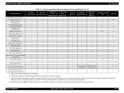
EPSON Stylus PHOTO 2100/2200 Revision B 5.1.3 Replacement Part-Based Adjustment Priorities The following table indicates the adjustment items and priorities on a replacement part ... USB ID input 3 IEEE-1394 ID input 3 Waste ink counter reset 1 Initial charge sequence 2 Powerful CL (Executed as required) 2 ...
EPSON Stylus PHOTO 2100/2200 Revision B 5.1.3 Replacement Part-Based Adjustment Priorities The following table indicates the adjustment items and priorities on a replacement part ... USB ID input 3 IEEE-1394 ID input 3 Waste ink counter reset 1 Initial charge sequence 2 Powerful CL (Executed as required) 2 ...
Service Manual
Page 195
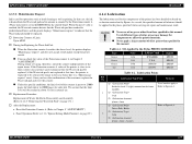
... be read /write Initial value write PG adjustment CR tooth skip prevention mechanism adjustment USB ID input IEEE-1394 ID input Waste ink counter reset Initial charge sequence Powerful CL Head ID input Head angular adjustment Bi-D adjustment Pixel shift adjustment PF adjustment PW sensor adjustment CR motor ...*d: Basically, peel the IEEE-1394 label applied to the old ASP mechanism and apply it to the specified position of the new mechanism. EPSON Stylus PHOTO 2100/2200 Revision B Adjustment Item Main board data read from the old board *b: When data cannot be read from the old board.
... be read /write Initial value write PG adjustment CR tooth skip prevention mechanism adjustment USB ID input IEEE-1394 ID input Waste ink counter reset Initial charge sequence Powerful CL Head ID input Head angular adjustment Bi-D adjustment Pixel shift adjustment PF adjustment PW sensor adjustment CR motor ...*d: Basically, peel the IEEE-1394 label applied to the old ASP mechanism and apply it to the specified position of the new mechanism. EPSON Stylus PHOTO 2100/2200 Revision B Adjustment Item Main board data read from the old board *b: When data cannot be read from the old board.

Service Manual
Page 198
... Top Menu Figure 5-4. Maintenance Top Menu " Check pattern printing Used to perform EEPROM data read/write, reset and paper passage test function (max. 100 pieces of board replacement. Figure 5-3. EPSON Stylus PHOTO 2100/2200 " Maintenance Used to reset the Waste ink pad counter, ink charge, perform cleaning, and copy the EEPROM data at the time of paper).
... Top Menu Figure 5-4. Maintenance Top Menu " Check pattern printing Used to perform EEPROM data read/write, reset and paper passage test function (max. 100 pieces of board replacement. Figure 5-3. EPSON Stylus PHOTO 2100/2200 " Maintenance Used to reset the Waste ink pad counter, ink charge, perform cleaning, and copy the EEPROM data at the time of paper).
Service Manual
Page 217
... Table 6-1. " You can check the value of the counter is preset to 25000 pages for black ink or to 10000 pages for color ink. We assume that time, the printer is not replaced at that the limit level will be ...printer has been decided on based on evaluation carried out by the Protection counter A (Waste ink counter) set in the EEPROM on page 29.) 6.1.4 Lubrication The lubrication used for repair in this manual. No. EPSON Stylus PHOTO 2100/2200 Revision B 6.1.3.2 Maintenance Request Ink is counted by Epson. After the Replacement: • Reset the Protection Counter...
... Table 6-1. " You can check the value of the counter is preset to 25000 pages for black ink or to 10000 pages for color ink. We assume that time, the printer is not replaced at that the limit level will be ...printer has been decided on based on evaluation carried out by the Protection counter A (Waste ink counter) set in the EEPROM on page 29.) 6.1.4 Lubrication The lubrication used for repair in this manual. No. EPSON Stylus PHOTO 2100/2200 Revision B 6.1.3.2 Maintenance Request Ink is counted by Epson. After the Replacement: • Reset the Protection Counter...

Service Manual
Page 229
...power supply 22 ENB I Detect signal for PW Table 7-8. Ground 12 CH O Charge signal for address counter of CSIC 25 GND - Ground 2LKy 21 GND2Lky - CN12-ASF sensor Pin Signal name I/O Function 1 ... 23 GND - Ground 16 SCK O Serial clock signal 17 GND 18 NC - Ground 24 CRST O Reset signal for the trapezoidal wave-form 13 VDD3.3 - +3.3V logic power supply 14 SP O SP signal 15... (M) 6 GND - Common voltage (B) - CN11-Printhead Pin Signal name I /O Function 9 GND - EPSON Stylus PHOTO 2100/2200 Table 7-7. Ground 2Lc 28 COMLm 29 GND2B -
...power supply 22 ENB I Detect signal for PW Table 7-8. Ground 12 CH O Charge signal for address counter of CSIC 25 GND - Ground 2LKy 21 GND2Lky - CN12-ASF sensor Pin Signal name I/O Function 1 ... 23 GND - Ground 16 SCK O Serial clock signal 17 GND 18 NC - Ground 24 CRST O Reset signal for the trapezoidal wave-form 13 VDD3.3 - +3.3V logic power supply 14 SP O SP signal 15... (M) 6 GND - Common voltage (B) - CN11-Printhead Pin Signal name I /O Function 9 GND - EPSON Stylus PHOTO 2100/2200 Table 7-7. Ground 2Lc 28 COMLm 29 GND2B -


