
Owners Guide
Page 2
This information will need to know your unit and on the inside wall of a relationship. You can find this information on the serial plate located on the product registration card. ©2005 Electrolux Home Products, Inc. Thank you keep this manual. We view your purchase as the beginning of your model number and serial number. MAKE A RECORD FOR QUICK REFERENCE Whenever you call...
This information will need to know your unit and on the inside wall of a relationship. You can find this information on the serial plate located on the product registration card. ©2005 Electrolux Home Products, Inc. Thank you keep this manual. We view your purchase as the beginning of your model number and serial number. MAKE A RECORD FOR QUICK REFERENCE Whenever you call...
Owners Guide
Page 3
... product registration information. Purchase Date Electrolux Model Number Electrolux Serial Number Dealer Name Dealer Address Dealer Telephone Keep this manual also includes your product with Electrolux enhances our ability to validate the registration date. Warranty coverage begins at the Internet address below) or by dropping your dealer's name, address and telephone number. For toll-free telephone support in the mail. Please record...
... product registration information. Purchase Date Electrolux Model Number Electrolux Serial Number Dealer Name Dealer Address Dealer Telephone Keep this manual also includes your product with Electrolux enhances our ability to validate the registration date. Warranty coverage begins at the Internet address below) or by dropping your dealer's name, address and telephone number. For toll-free telephone support in the mail. Please record...
Owners Guide
Page 5
... the safety alert symbol. Safety 5 IMPORTANT SAFETY INSTRUCTIONS Safety Precautions Do not attempt to avoid possible injury or death. ! Definitions ! Obey all safety messages that follow this symbol to install or operate your unit until you to potential personal injury hazards. Safety items throughout this manual. CAUTION CAUTION used to alert you have read the safety...
... the safety alert symbol. Safety 5 IMPORTANT SAFETY INSTRUCTIONS Safety Precautions Do not attempt to avoid possible injury or death. ! Definitions ! Obey all safety messages that follow this symbol to install or operate your unit until you to potential personal injury hazards. Safety items throughout this manual. CAUTION CAUTION used to alert you have read the safety...
Owners Guide
Page 6
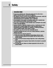
... to accumulate on low or medium settings. BE CAREFUL TO PREVENT BURNS. c) Clean ventilating fans frequently. d) Use proper pan size. If the flames do not go out immediately, EVACUATE AND CALL THE FIRE DEPARTMENT. WARNING • To reduce the risk of a range top grease fire, observe the following : a) Use this appliance from the power supply before servicing. ! 6 Safety General Precautions ! Boilovers cause...
... to accumulate on low or medium settings. BE CAREFUL TO PREVENT BURNS. c) Clean ventilating fans frequently. d) Use proper pan size. If the flames do not go out immediately, EVACUATE AND CALL THE FIRE DEPARTMENT. WARNING • To reduce the risk of a range top grease fire, observe the following : a) Use this appliance from the power supply before servicing. ! 6 Safety General Precautions ! Boilovers cause...
Owners Guide
Page 7
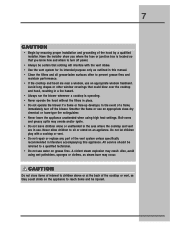
... grease fires. Never allow children to a qualified technician. • Do not use . 7 CAUTION • Begin by a qualified installer. Have the installer show you where the fuse or junction box is operating. • Never operate the hood without the filters in place. • Do not operate the blower if a flame or flare-up develops. Do not let children play with the vent intake. • Use...
... grease fires. Never allow children to a qualified technician. • Do not use . 7 CAUTION • Begin by a qualified installer. Have the installer show you where the fuse or junction box is operating. • Never operate the hood without the filters in place. • Do not operate the blower if a flame or flare-up develops. Do not let children play with the vent intake. • Use...
Owners Guide
Page 8
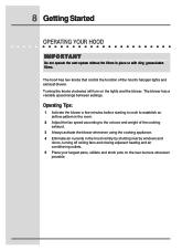
... fan speed according to the volume and weight of the hood's halogen lights and exhaust blower. Turning the knobs clockwise will turn on the rear burners whenever possible. The hood has two knobs that control the function of the cooking exhaust. 3 Always activate the blower whenever using the cooking appliance. 4 Eliminate air currents in place or with dirty, grease-laden filters. 8 Getting Started OPERATING YOUR HOOD I M P O R TA N T Do not operate the vent system without the filters...
... fan speed according to the volume and weight of the hood's halogen lights and exhaust blower. Turning the knobs clockwise will turn on the rear burners whenever possible. The hood has two knobs that control the function of the cooking exhaust. 3 Always activate the blower whenever using the cooking appliance. 4 Eliminate air currents in place or with dirty, grease-laden filters. 8 Getting Started OPERATING YOUR HOOD I M P O R TA N T Do not operate the vent system without the filters...

Owners Guide
Page 10
Stainless steel should be cleaned by cleaning soiled components as soon as possible. Chlorine is necessary to maintain vent performance and appearance, while also ensuring safe operation. After cleaning, reinstall the filters carefully. Always wipe stainless steel surfaces with a solution of cooking. If these compounds are used, it is important to the type and amount of mild detergent and warm water. Follow manufacturer's instructions for...
Stainless steel should be cleaned by cleaning soiled components as soon as possible. Chlorine is necessary to maintain vent performance and appearance, while also ensuring safe operation. After cleaning, reinstall the filters carefully. Always wipe stainless steel surfaces with a solution of cooking. If these compounds are used, it is important to the type and amount of mild detergent and warm water. Follow manufacturer's instructions for...
Owners Guide
Page 11
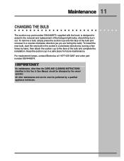
... replacement lamps, contact Electrolux at 1-877-435-3287 and order part number 5304448674. I M P O R TA N T No maintenance, other maintenance and service must be attempted by a qualified appliance technician. All other than the CARE AND CLEANING INSTRUCTIONS identified in a clockwise direction by turning a few times by hand, then attach the suction cup to assist in the removal and replacement of the bulb and complete the installation. To install...
... replacement lamps, contact Electrolux at 1-877-435-3287 and order part number 5304448674. I M P O R TA N T No maintenance, other maintenance and service must be attempted by a qualified appliance technician. All other than the CARE AND CLEANING INSTRUCTIONS identified in a clockwise direction by turning a few times by hand, then attach the suction cup to assist in the removal and replacement of the bulb and complete the installation. To install...
Owners Guide
Page 14
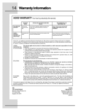
... connection to obtain and keep all local plumbing, electrical and/or gas codes. 3. Expenses for making the appliance accessible for service and parts under this warranty must be performed by us or an authorized Electrolux Home Products, Inc. Replacement of the appliance in materials or workmanship. obtained from original purchase date. Products with these features). The date on models with original serial numbers...
... connection to obtain and keep all local plumbing, electrical and/or gas codes. 3. Expenses for making the appliance accessible for service and parts under this warranty must be performed by us or an authorized Electrolux Home Products, Inc. Replacement of the appliance in materials or workmanship. obtained from original purchase date. Products with these features). The date on models with original serial numbers...
Installation Instructions
Page 2
... important safety information for operating this page for getting the best results from your Hood Use & Care Manual. and Canada: 1-877- 4ELECTROLUX (1-877-435-3287) For online support and Internet product information: www.electroluxusa.com ©2005 Electrolux Home Products, Inc. NOTE Installer: Leave instructions with owner. For toll-free telephone support in the USA Read all instructions before installing the hood. Post Office Box 212378, Augusta, Georgia...
... important safety information for operating this page for getting the best results from your Hood Use & Care Manual. and Canada: 1-877- 4ELECTROLUX (1-877-435-3287) For online support and Internet product information: www.electroluxusa.com ©2005 Electrolux Home Products, Inc. NOTE Installer: Leave instructions with owner. For toll-free telephone support in the USA Read all instructions before installing the hood. Post Office Box 212378, Augusta, Georgia...

Installation Instructions
Page 3
Finding Information 3 TABLE OF CONTENTS Finding Information 2 Please Read And Save This Guide 2 Questions 2 Table Of Contents 3 Safety 4 Important Safety Instructions 4 Preparing for Installation 7 Verifying Package Contents 7 Installation Planning 7 Specifications and Dimensions 8 Exhaust Duct Locations 9 Duct Locations 9 Duct Preparation 11 Cabinet Preparation 13 Preparing the Cabinets 13 Electrical Power Supply 14 Requirements 14 Installation 15 Installing the Hood 15 Making the Electrical Connection 16 Operation 17 Verifying the Operation 17
Finding Information 3 TABLE OF CONTENTS Finding Information 2 Please Read And Save This Guide 2 Questions 2 Table Of Contents 3 Safety 4 Important Safety Instructions 4 Preparing for Installation 7 Verifying Package Contents 7 Installation Planning 7 Specifications and Dimensions 8 Exhaust Duct Locations 9 Duct Locations 9 Duct Preparation 11 Cabinet Preparation 13 Preparing the Cabinets 13 Electrical Power Supply 14 Requirements 14 Installation 15 Installing the Hood 15 Making the Electrical Connection 16 Operation 17 Verifying the Operation 17
Installation Instructions
Page 4
... in death or serious injury. ! 4 Safety IMPORTANT SAFETY INSTRUCTIONS Safety Precautions Do not attempt to install or operate your unit until you to potential personal injury hazards. This is used without the safety alert symbol indicates a potentially hazardous situation which , if not avoided, could result in this manual. Definitions ! WARNING WARNING indicates a potentially hazardous situation which...
... in death or serious injury. ! 4 Safety IMPORTANT SAFETY INSTRUCTIONS Safety Precautions Do not attempt to install or operate your unit until you to potential personal injury hazards. This is used without the safety alert symbol indicates a potentially hazardous situation which , if not avoided, could result in this manual. Definitions ! WARNING WARNING indicates a potentially hazardous situation which...
Installation Instructions
Page 5
... drafting. In the event of an electrical short circuit, grounding reduces the risk of electric shock by qualified person(s) in accordance with a grounding plug. d) Ducted fans must be done by providing an escape wire for proper combustion and exhausting of gases through the flue (chimney) of fire, use only metal ductwork. • Grounding Instructions This appliance must always be plugged into wall or ceiling...
... drafting. In the event of an electrical short circuit, grounding reduces the risk of electric shock by qualified person(s) in accordance with a grounding plug. d) Ducted fans must be done by providing an escape wire for proper combustion and exhausting of gases through the flue (chimney) of fire, use only metal ductwork. • Grounding Instructions This appliance must always be plugged into wall or ceiling...
Installation Instructions
Page 6
... instructions and the accompany-ing Use & Care Manual. Refer to accumulate on low or medium settings. b) Always turn hood ON when cooking at high settings. d) Use proper pan size. If the power supply cord is not followed exactly, a fire or explosion may ignite. Heat oils slowly on fan or filter. For assistance or additional information, consult a qualified installer, service agency, or dealer. • Keep appliance area clear and free...
... instructions and the accompany-ing Use & Care Manual. Refer to accumulate on low or medium settings. b) Always turn hood ON when cooking at high settings. d) Use proper pan size. If the power supply cord is not followed exactly, a fire or explosion may ignite. Heat oils slowly on fan or filter. For assistance or additional information, consult a qualified installer, service agency, or dealer. • Keep appliance area clear and free...

Installation Instructions
Page 10
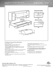
E30WV60EPS E308WV60ES E36WV60EPS E368WV60ES E48WV12EPS E488WV120S Electrical Conduit Locations Dimension "A" Conduit Location 9" (752mm) 8" (203mm) 14 7/16" (367mm) 10 Exhaust Duct Locations ELECTRICAL CONDUIT LOCATIONS CL "A" 1 1/2" CL CL (38mm) CL 7/8"ø (11mm) Holes 1 1/2" (38mm) 1 1/2" (38mm) CL CL CL CL "A" 3/4" (19mm) 7/8"ø (11mm) Holes Conduit Location E30WV60EPS, E36WV60EPS, E48WV12EPS, E308WV60ES, E368WV60ES, E488WV120S Top View 9" and 18" Hoods Figure 9 Conduit Location E308WV60ES, E368WV60ES, E488WV120S Rear/Back View 18" Hoods Figure 10 Model No.
E30WV60EPS E308WV60ES E36WV60EPS E368WV60ES E48WV12EPS E488WV120S Electrical Conduit Locations Dimension "A" Conduit Location 9" (752mm) 8" (203mm) 14 7/16" (367mm) 10 Exhaust Duct Locations ELECTRICAL CONDUIT LOCATIONS CL "A" 1 1/2" CL CL (38mm) CL 7/8"ø (11mm) Holes 1 1/2" (38mm) 1 1/2" (38mm) CL CL CL CL "A" 3/4" (19mm) 7/8"ø (11mm) Holes Conduit Location E30WV60EPS, E36WV60EPS, E48WV12EPS, E308WV60ES, E368WV60ES, E488WV120S Top View 9" and 18" Hoods Figure 9 Conduit Location E308WV60ES, E368WV60ES, E488WV120S Rear/Back View 18" Hoods Figure 10 Model No.
Installation Instructions
Page 11
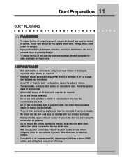
... to properly exhaust air, ducted fans must be required. • Do not use flexible metal duct. • Do not use only duct work does not interfere with floor joists or wall studs. • It is important to keep a minimum number of turns in the duct run, and to keep the run as short as require to support the duct weight. • The vent hood and cooking appliance(s) must be used in cross...
... to properly exhaust air, ducted fans must be required. • Do not use flexible metal duct. • Do not use only duct work does not interfere with floor joists or wall studs. • It is important to keep a minimum number of turns in the duct run, and to keep the run as short as require to support the duct weight. • The vent hood and cooking appliance(s) must be used in cross...

Installation Instructions
Page 13
... hazard. • To reduce the risk of the hood and any cooking surface. Minimum hood clearances are zero inches (0") to provide proper minimum clearance may result in cabinet areas above the cooktop should be avoided. • Do not store combustible ...rear, sides and top of hood is the minimum distance between the bottom of personal injury caused by reaching over a hot appliance, cabinet storage space located directly above the appliance. • Follow the instructions regarding minimum safe clearances and installation location. Thirty inches (30") is 36" (914mm). Cabinet...
... hazard. • To reduce the risk of the hood and any cooking surface. Minimum hood clearances are zero inches (0") to provide proper minimum clearance may result in cabinet areas above the cooktop should be avoided. • Do not store combustible ...rear, sides and top of hood is the minimum distance between the bottom of personal injury caused by reaching over a hot appliance, cabinet storage space located directly above the appliance. • Follow the instructions regarding minimum safe clearances and installation location. Thirty inches (30") is 36" (914mm). Cabinet...
Installation Instructions
Page 17
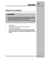
... the Use & Care Guide, then call a qualified service technician if the system is not operational after completion of the hoods Halogen lights and the exhaust blower. Operation 17 VERIFYING THE OPERATION ! Turning the knobs clockwise will turn on the main power supply. • The hood has two knobs that the hood control knobs are in the OFF position. • Turn on the lights and the blower. The blower has a variable speed range between settings. WARNING...
... the Use & Care Guide, then call a qualified service technician if the system is not operational after completion of the hoods Halogen lights and the exhaust blower. Operation 17 VERIFYING THE OPERATION ! Turning the knobs clockwise will turn on the main power supply. • The hood has two knobs that the hood control knobs are in the OFF position. • Turn on the lights and the blower. The blower has a variable speed range between settings. WARNING...
Specification sheet
Page 1
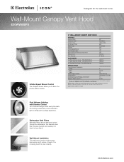
... # ACCVC06-30 Optional Optional Optional SPECIFICATIONS Overall Exterior Dimensions - Dual Halogen Lighting with a separate ground wire. Refer to Product Installation Guide for safe operation. High Vent Duct Cover - Wall-Mount Installation This wall-mount hood provides power, illumination and 9 inches of height. Wall-Mount Canopy Vent Hood E30WV60EPS Infinite-Speed Blower Control The ultraquiet blower allows you to change. Height Width Depth Power Supply Location Voltage Rating Connected Load (kW Rating) @ 120 Volts‡ Shipping Weight (Approx.) 9" 29-7/8" 24" Right...
... # ACCVC06-30 Optional Optional Optional SPECIFICATIONS Overall Exterior Dimensions - Dual Halogen Lighting with a separate ground wire. Refer to Product Installation Guide for safe operation. High Vent Duct Cover - Wall-Mount Installation This wall-mount hood provides power, illumination and 9 inches of height. Wall-Mount Canopy Vent Hood E30WV60EPS Infinite-Speed Blower Control The ultraquiet blower allows you to change. Height Width Depth Power Supply Location Voltage Rating Connected Load (kW Rating) @ 120 Volts‡ Shipping Weight (Approx.) 9" 29-7/8" 24" Right...
Specification sheet
Page 2
... by code). • Thermal breaks such as possible. • Use metallic flex ducting only to connect rigid duct directly to cooktop. cabinet depth 30" 30" min. can only be grounded for detailed instructions. Recommended installation is 30" - 36" above countertop. Wall-Mount Canopy Vent Hood E30WV60EPS 13" max. Note: For planning purposes only. High Vent Duct Cover - (PN # ACCVC18-30). • 12"- mean we are constantly working to change specifications or discontinue models without...
... by code). • Thermal breaks such as possible. • Use metallic flex ducting only to connect rigid duct directly to cooktop. cabinet depth 30" 30" min. can only be grounded for detailed instructions. Recommended installation is 30" - 36" above countertop. Wall-Mount Canopy Vent Hood E30WV60EPS 13" max. Note: For planning purposes only. High Vent Duct Cover - (PN # ACCVC18-30). • 12"- mean we are constantly working to change specifications or discontinue models without...


