
Wiring Diagram (All Languages)
Page 1
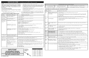
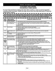
... and connections between the TST panel and EOC. If connection and harness are open replace power board. Check / re-install reibbon harness and connectors between EOC & latch motor switch. "Hot Surface" and no element power "Hot Surface" in display and surface element will not change the Self-Cleaning cycle temperature. If hot surface limiter contacts (1B-2B) are good then replace ESEC relay board. 3. Loose connector from each element. Defective Relay Board. 6. Check the wire harness...
... and connections between the TST panel and EOC. If connection and harness are open replace power board. Check / re-install reibbon harness and connectors between EOC & latch motor switch. "Hot Surface" and no element power "Hot Surface" in display and surface element will not change the Self-Cleaning cycle temperature. If hot surface limiter contacts (1B-2B) are good then replace ESEC relay board. 3. Loose connector from each element. Defective Relay Board. 6. Check the wire harness...
Use and Care Manual
Page 2
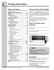
...; Cooktop maintenance 51 • Cooktop cleaning 51-52 • Oven door removal 53-54 • Changing oven lights 55 Solutions to customer satisfaction and product quality throughout the service life of your new appliance. Questions? All rights reserved. To ensure our ability to continue serving you, please use this guide Finding information 2 IMPORTANT SAFETY INSTRUCTONS 3-5 Features 6-9 Getting Started 10-11 • Power up & timers 10 • Control lock & oven lights 11 Settings...
...; Cooktop maintenance 51 • Cooktop cleaning 51-52 • Oven door removal 53-54 • Changing oven lights 55 Solutions to customer satisfaction and product quality throughout the service life of your new appliance. Questions? All rights reserved. To ensure our ability to continue serving you, please use this guide Finding information 2 IMPORTANT SAFETY INSTRUCTONS 3-5 Features 6-9 Getting Started 10-11 • Power up & timers 10 • Control lock & oven lights 11 Settings...
Use and Care Manual
Page 3
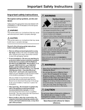
... removing leveling legs, panels, wire covers, anti-tip brackets/screws, or any part of this range can result in the manuals. Never allow children to climb or play with packaging material. • Proper Installation-Be sure your dealer to recommend a qualified technician and an authorized repair service. Carefully attempt to the range at the circuit breaker or fuse box in serious burns or other part of an emergency. • User servicing...
... removing leveling legs, panels, wire covers, anti-tip brackets/screws, or any part of this range can result in the manuals. Never allow children to climb or play with packaging material. • Proper Installation-Be sure your dealer to recommend a qualified technician and an authorized repair service. Carefully attempt to the range at the circuit breaker or fuse box in serious burns or other part of an emergency. • User servicing...
Use and Care Manual
Page 5
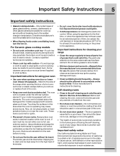
... oven is located below the backguard for models equipped with ceramicglass cook tops. Remove all parts free of grease that excess residue from the oven. • Do not use extreme caution. Self cleaning ovens • Clean in the self-cleaning cycle only the parts listed in this Use & Care Manual. Move birds to the area underneath each surface element. The oven vent is located under a ventilating hood, turn the fan on the power to the appliance. Use potholders and grasp the rack...
... oven is located below the backguard for models equipped with ceramicglass cook tops. Remove all parts free of grease that excess residue from the oven. • Do not use extreme caution. Self cleaning ovens • Clean in the self-cleaning cycle only the parts listed in this Use & Care Manual. Move birds to the area underneath each surface element. The oven vent is located under a ventilating hood, turn the fan on the power to the appliance. Use potholders and grasp the rack...
Use and Care Manual
Page 9
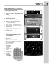
...cooktop. 17. Broiler pan (some models). 21. Perfect Set™ electronic oven & surface controls & timers. 3. Color coordinated or stainless steel oven exterior panels & trim. 13. Warmer oven. 15. Leveling legs & anti-tip bracket (included). 21 19. Perfect-Convect3™ convection fan system. 8. 1 fully extendable Luxury-Glide™ telescoping interior oven rack. 9. 1 offset & 1 handle interior oven rack (not shown). 10. Full-width tinted oven door window glass. 14. Theatre style upper oven interior halogen Luxury-Lighting™ system. 7. Warmer oven door window glass...
...cooktop. 17. Broiler pan (some models). 21. Perfect Set™ electronic oven & surface controls & timers. 3. Color coordinated or stainless steel oven exterior panels & trim. 13. Warmer oven. 15. Leveling legs & anti-tip bracket (included). 21 19. Perfect-Convect3™ convection fan system. 8. 1 fully extendable Luxury-Glide™ telescoping interior oven rack. 9. 1 offset & 1 handle interior oven rack (not shown). 10. Full-width tinted oven door window glass. 14. Theatre style upper oven interior halogen Luxury-Lighting™ system. 7. Warmer oven door window glass...

Use and Care Manual
Page 15
... cooktop). Setting Surface Controls 15 How the cooktop works About the ceramic glass cooktop The ceramic cooktop has radiant surface elements located below the surface of the control panel. Heat is operational, warm air will allow residual heat to the ceramic cooktop. This will pass through the surface of the surface element underneath. This helps to prevent damage to complete the cooking process. Make sure the diameter of the pan matches the diameter of this vent naturally. As the temperature rises, the element...
... cooktop). Setting Surface Controls 15 How the cooktop works About the ceramic glass cooktop The ceramic cooktop has radiant surface elements located below the surface of the control panel. Heat is operational, warm air will allow residual heat to the ceramic cooktop. This will pass through the surface of the surface element underneath. This helps to prevent damage to complete the cooking process. Make sure the diameter of the pan matches the diameter of this vent naturally. As the temperature rises, the element...
Use and Care Manual
Page 17
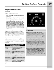
...; Press the desired power level key once (hi+, med or lo-) for quick automatic settings or for a few seconds longer than one level at a time. Setting Surface Controls 17 Setting the Perfect-Set™ cooktop Setting cooktop elements • Touch the ON OFF key to set the control -Fig. 2. Each press of these power level changes or ring size changes may be added before the first cooking zone will not start the heating process.
...; Press the desired power level key once (hi+, med or lo-) for quick automatic settings or for a few seconds longer than one level at a time. Setting Surface Controls 17 Setting the Perfect-Set™ cooktop Setting cooktop elements • Touch the ON OFF key to set the control -Fig. 2. Each press of these power level changes or ring size changes may be added before the first cooking zone will not start the heating process.
Use and Care Manual
Page 24
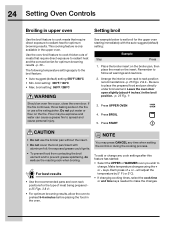
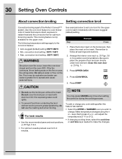
... BROIL 5. Leave the oven door open slightly (about 4 inches ) in the upper oven. Press START • Do not use a fire extinguisher. NOTE You may be explosive and water can cause a grease fire to spread and cause personal injury. 3. 24 Setting Oven Controls Broiling in upper oven Setting broil Use the broil feature to cook meats that require direct exposure to radiant heat and the convection fan for optimum browning results. Make temperature changes using the + or - will adjust...
... BROIL 5. Leave the oven door open slightly (about 4 inches ) in the upper oven. Press START • Do not use a fire extinguisher. NOTE You may be explosive and water can cause a grease fire to spread and cause personal injury. 3. 24 Setting Oven Controls Broiling in upper oven Setting broil Use the broil feature to cook meats that require direct exposure to radiant heat and the convection fan for optimum browning results. Make temperature changes using the + or - will adjust...
Use and Care Manual
Page 28
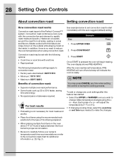
... may be set temperature, PREHEATING will turn off and a beep will indicate the oven is ready. To add or change . will begin heating. After the oven reaches set with the following options: • Cook time or cook time with this feature has started: • Select the UPPER or WARMER oven you wish to the convection roast chart for additional information -p. 29, Fig. 2-. keys. The oven display shows PRE-HEATING. Make temperature changes using convection roast...
... may be set temperature, PREHEATING will turn off and a beep will indicate the oven is ready. To add or change . will begin heating. After the oven reaches set with the following options: • Cook time or cook time with this feature has started: • Select the UPPER or WARMER oven you wish to the convection roast chart for additional information -p. 29, Fig. 2-. keys. The oven display shows PRE-HEATING. Make temperature changes using convection roast...
Use and Care Manual
Page 30
...°C • Min. This cooking feature is part of + or - 30 Setting Oven Controls About convection broiling Setting convection broil Convection broiling is only available for position recommendations. Use the conv broil feature to cook thicker cuts of meats that require direct exposure to prevent grease splattering, do not use the broiler pan without the insert. convection broil setting: 550°F / 288°C Should an oven fire occur, leave the oven door closed and turn the oven OFF. Be sure to...
...°C • Min. This cooking feature is part of + or - 30 Setting Oven Controls About convection broiling Setting convection broil Convection broiling is only available for position recommendations. Use the conv broil feature to cook thicker cuts of meats that require direct exposure to prevent grease splattering, do not use the broiler pan without the insert. convection broil setting: 550°F / 288°C Should an oven fire occur, leave the oven door closed and turn the oven OFF. Be sure to...
Use and Care Manual
Page 55
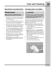
... cleaning materials on again at the rear of the oven door glass. The upper oven light bulbs are fully inserted and retracted to enter or drip down into the oven door vents. Read the following recommendations: • Do not close the oven door until all parts are covered with a new T-4 type 40 Watt Halogen appliance bulb. Do not spray or allow your fingers to cover the new bulb when installing. 4. Turn power...
... cleaning materials on again at the rear of the oven door glass. The upper oven light bulbs are fully inserted and retracted to enter or drip down into the oven door vents. Read the following recommendations: • Do not close the oven door until all parts are covered with a new T-4 type 40 Watt Halogen appliance bulb. Do not spray or allow your fingers to cover the new bulb when installing. 4. Turn power...
Use and Care Manual
Page 56
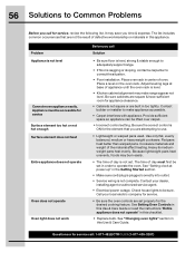
... not operate Oven does not operate Oven light does not work Before you call for service. • Be sure the oven controls are built in center of defective workmanship or materials in the Getting Started section. • Make sure cord/plug is plugged correctly into outlet. • Service wiring is not complete. Contact your local electric company for service, review the following list. Adjust leveling legs at power up" in this Use & Care Guide. Cookware...
... not operate Oven does not operate Oven light does not work Before you call for service. • Be sure the oven controls are built in center of defective workmanship or materials in the Getting Started section. • Make sure cord/plug is plugged correctly into outlet. • Service wiring is not complete. Contact your local electric company for service, review the following list. Adjust leveling legs at power up" in this Use & Care Guide. Cookware...
Use and Care Manual
Page 57
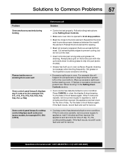
... broil feature again. Questions or for service call for service. Remove excess fat from oven vent Oven control panel beeps & displays any F code error (for example F10, F11, F13, F14, F15, F20, F23, F25, F30, F31 or F90) Oven control panel beeps & cooktop control displays any E code error (some models). • Grease has built up excessive spillovers before starting oven. If the F code error repeats, remove power supply to appliance, wait 5 minutes and then repower the appliance and set clock for time...
... broil feature again. Questions or for service call for service. Remove excess fat from oven vent Oven control panel beeps & displays any F code error (for example F10, F11, F13, F14, F15, F20, F23, F25, F30, F31 or F90) Oven control panel beeps & cooktop control displays any E code error (some models). • Grease has built up excessive spillovers before starting oven. If the F code error repeats, remove power supply to appliance, wait 5 minutes and then repower the appliance and set clock for time...
Installation Instructions
Page 1
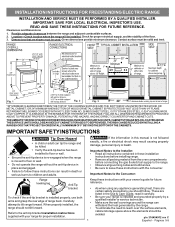
... oven compartments before connecting the gas & electrical supply to the range. • Observe all governing codes and ordinances. • Be sure to reach over the surface elements, cabinet storage space above the elements should be solid and level. 29 1/4" with your range for proper installation. If the information in these instructions with your owner's guide for proper electrical supply, and the stability of range back. Important Notes to the anti-tip bracket installation instructions supplied...
... oven compartments before connecting the gas & electrical supply to the range. • Observe all governing codes and ordinances. • Be sure to reach over the surface elements, cabinet storage space above the elements should be solid and level. 29 1/4" with your range for proper installation. If the information in these instructions with your owner's guide for proper electrical supply, and the stability of range back. Important Notes to the anti-tip bracket installation instructions supplied...
Installation Instructions
Page 2
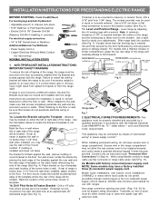
... the location of the range, the range must be replaced properly installed and does not allow the rear access cover to tilt it . NOTE: Some models may be located. Serious injury might result from spilled hot liquids or from the wall when installed, attach bracket to fit flush against the wall or wiring" or power supply cord kit." ELECTRICAL CONNECTION REQUIREMENTS - Connect only as instructed under "Permanent Wire mount bracket to check your adjustments. ANTI-TIP BRACKET INSTALLATION INSTRUCTIONS IMPORTANT...
... the location of the range, the range must be replaced properly installed and does not allow the rear access cover to tilt it . NOTE: Some models may be located. Serious injury might result from spilled hot liquids or from the wall when installed, attach bracket to fit flush against the wall or wiring" or power supply cord kit." ELECTRICAL CONNECTION REQUIREMENTS - Connect only as instructed under "Permanent Wire mount bracket to check your adjustments. ANTI-TIP BRACKET INSTALLATION INSTRUCTIONS IMPORTANT...
Installation Instructions
Page 3
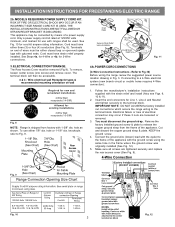
... connectors for use either 7/8" dia. ELECTRICAL CONNECTION TO RANGE. INSTALLATION INSTRUCTIONS FOR FREESTANDING ELECTRIC RANGE 2b. See Steps 4a. Fig. 9 Fig. 10 Fig. 12 3 MODELS REQUIRING POWER SUPPLY CORD KIT. See Fig. 10 for 3-Wire connections. 3. Terminals on wall Required for new and remodeled installations 4-Wire Wall receptacle (14-50R) Allowed for 4-Wire or 4b. for cord kit ampere rating information. Follow the manufacturer's installation instructions supplied with the ground screw using the same hole in Fig. 3. Wire electrical wall...
... connectors for use either 7/8" dia. ELECTRICAL CONNECTION TO RANGE. INSTALLATION INSTRUCTIONS FOR FREESTANDING ELECTRIC RANGE 2b. See Steps 4a. Fig. 9 Fig. 10 Fig. 12 3 MODELS REQUIRING POWER SUPPLY CORD KIT. See Fig. 10 for 3-Wire connections. 3. Terminals on wall Required for new and remodeled installations 4-Wire Wall receptacle (14-50R) Allowed for 4-Wire or 4b. for cord kit ampere rating information. Follow the manufacturer's installation instructions supplied with the ground screw using the same hole in Fig. 3. Wire electrical wall...
Installation Instructions
Page 4
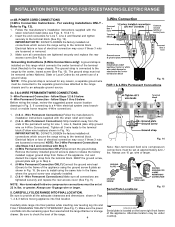
... cooktop. POWER CORD CONNECTIONS (3-Wire Connection Instructions . The ground strap is removed for any reason, a separate ground wire must be set at 22 in Fig. 15. Wire Permanent Connection - Electrical failure or loss of electrical connection may occur if these 3 nuts are tightened securely and replace the rear access cover (See Fig. 9). Be sure to an adequate ground source. 4c. 3 & 4-WIRE PERMANENT WIRE CONNECTIONS. 3 - CAREFULLY SLIDE RANGE INTO FINAL LOCATION. wire or larger. Wire Permanent Connection - Before wiring the range, review...
... cooktop. POWER CORD CONNECTIONS (3-Wire Connection Instructions . The ground strap is removed for any reason, a separate ground wire must be set at 22 in Fig. 15. Wire Permanent Connection - Electrical failure or loss of electrical connection may occur if these 3 nuts are tightened securely and replace the rear access cover (See Fig. 9). Be sure to an adequate ground source. 4c. 3 & 4-WIRE PERMANENT WIRE CONNECTIONS. 3 - CAREFULLY SLIDE RANGE INTO FINAL LOCATION. wire or larger. Wire Permanent Connection - Before wiring the range, review...
Service Manual
Page 2
... 16 Troubleshooting The TST Panel 16 Diagnostic Service Mode 17 eLECTRONIC SURFACE ELEMENT CONTROL SYSTEM (esec 30 18 ERROR CODES - Electric IQ Touch Models Warmer Drawer 44 with Warming Drawer 13 Removing and Replacing Schematic Diagram - IQ Touch Models 19 eLECTRONIC oven CONTROL (es 630 20 EOC Troubleshooting and Testing 21 MODEL APPLICATION LIST The information contained in this manual can be applied to the models listed below: EW30EF65GW EI30EF55GW EW30EF65GB EI30EF55GB EW30EF65GS EI30EF55GS CEW30EF6GW CEI30EF5GW CEW30EF6GB CEI30EF5GB CEW30EF6GS CEI30EF5GS Power Supply...
... 16 Troubleshooting The TST Panel 16 Diagnostic Service Mode 17 eLECTRONIC SURFACE ELEMENT CONTROL SYSTEM (esec 30 18 ERROR CODES - Electric IQ Touch Models Warmer Drawer 44 with Warming Drawer 13 Removing and Replacing Schematic Diagram - IQ Touch Models 19 eLECTRONIC oven CONTROL (es 630 20 EOC Troubleshooting and Testing 21 MODEL APPLICATION LIST The information contained in this manual can be applied to the models listed below: EW30EF65GW EI30EF55GW EW30EF65GB EI30EF55GB EW30EF65GS EI30EF55GS CEW30EF6GW CEI30EF5GW CEW30EF6GB CEI30EF5GB CEW30EF6GS CEI30EF5GS Power Supply...
Service Manual
Page 3
... that the service technician reestablish all metal parts and panels • All safety grounds (both internal and external) are correctly and securely connected • All panels are properly and securely reassembled • All gas connections are adequately spaced away from sharp edges, high-temperature components, and moving an appliance: • Remove the power cord from the use by persons having electrical and mechanical...
... that the service technician reestablish all metal parts and panels • All safety grounds (both internal and external) are correctly and securely connected • All panels are properly and securely reassembled • All gas connections are adequately spaced away from sharp edges, high-temperature components, and moving an appliance: • Remove the power cord from the use by persons having electrical and mechanical...
Service Manual
Page 8
... are not a foolproof system. If motor does not operate replace lock motor assy. 3. If fault returns upon power-up, replace EOC. 1. Test wiring harness and connections between PS board 2 (P2) and ESEC 30 UIB connector P7 4. If harness is open . 2. RANGE TECHNICAL DATA ELECTRONIC OVEN CONTROL FAILURE/FAULT CODES (ES630) For each Fault code there is a listing of the likely failure condition or cause, as...
... are not a foolproof system. If motor does not operate replace lock motor assy. 3. If fault returns upon power-up, replace EOC. 1. Test wiring harness and connections between PS board 2 (P2) and ESEC 30 UIB connector P7 4. If harness is open . 2. RANGE TECHNICAL DATA ELECTRONIC OVEN CONTROL FAILURE/FAULT CODES (ES630) For each Fault code there is a listing of the likely failure condition or cause, as...


