
User Manual
Page 2
... may appear slightly different from any defect in the software. The software and specifications are trademarks and/or registered trademarks of such revision or changes. reserves the right to revise this manual is sold or licensed as is. The product you have purchased and the setup screen may be reproduced, transmitted, transcribed, stored in a retrieval system, or translated...
... may appear slightly different from any defect in the software. The software and specifications are trademarks and/or registered trademarks of such revision or changes. reserves the right to revise this manual is sold or licensed as is. The product you have purchased and the setup screen may be reproduced, transmitted, transcribed, stored in a retrieval system, or translated...
User Manual
Page 3
Contents Chapter 1: Introduction ...3 1.1 Product Features...3 1.2 Application ...3 1.3 Compatibility...3 1.4 System Requirements ...4 Chapter 2: Adapter ...5 2.1 Ethernet Ports ...5 2.2 Buttons...5 2.3 LEDs...5 Chapter 3: Utility Software Installation ...6 Chapter 4: Using the Utility Software ...13 4.1 Main Tab ...13 4.2 Privacy Tab ...14 4.3 Diagnostics Tab ...15 4.4 About Tab...16 Chapter 5: NMK(GROUP) Button ...17 5.1 Forming a HomePlug AV Logical Network 17 5.2 Joining a Network ...17 5.3 Leaving a Network ...18 2
Contents Chapter 1: Introduction ...3 1.1 Product Features...3 1.2 Application ...3 1.3 Compatibility...3 1.4 System Requirements ...4 Chapter 2: Adapter ...5 2.1 Ethernet Ports ...5 2.2 Buttons...5 2.3 LEDs...5 Chapter 3: Utility Software Installation ...6 Chapter 4: Using the Utility Software ...13 4.1 Main Tab ...13 4.2 Privacy Tab ...14 4.3 Diagnostics Tab ...15 4.4 About Tab...16 Chapter 5: NMK(GROUP) Button ...17 5.1 Forming a HomePlug AV Logical Network 17 5.2 Joining a Network ...17 5.3 Leaving a Network ...18 2
User Manual
Page 4
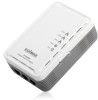
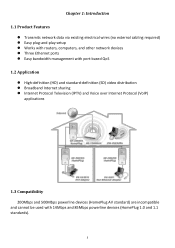
Chapter 1: Introduction 1.1 Product Features Transmits network data via existing electrical wires (no external cabling required) Easy plug-and-play setup Works with routers, computers, and other network devices Three Ethernet ports Easy bandwidth management with port-based QoS 1.2 Application High-definition (HD) and standard-definition (SD) video distribution Broadband Internet sharing Internet Protocol Television (IPTV...
Chapter 1: Introduction 1.1 Product Features Transmits network data via existing electrical wires (no external cabling required) Easy plug-and-play setup Works with routers, computers, and other network devices Three Ethernet ports Easy bandwidth management with port-based QoS 1.2 Application High-definition (HD) and standard-definition (SD) video distribution Broadband Internet sharing Internet Protocol Television (IPTV...

User Manual
Page 6
... adapter's NMK value; Press and hold the NMK(GROUP) button for 3 seconds to add the powerline adapter to factory defaults. or press and hold the network management key (NMK(GROUP)) button for 3 seconds to restore the powerline adapter to the existing AV logical network (AVLN). 2.3 LEDs 1-3 (Ethernet Ports) Power PLC Indicates activity in the Ethernet connection Indicates the power status of the powerline adapter Indicates activity in the powerline connection 5 Additionally, the HP-2002ES supports port...
... adapter's NMK value; Press and hold the NMK(GROUP) button for 3 seconds to add the powerline adapter to factory defaults. or press and hold the network management key (NMK(GROUP)) button for 3 seconds to restore the powerline adapter to the existing AV logical network (AVLN). 2.3 LEDs 1-3 (Ethernet Ports) Power PLC Indicates activity in the Ethernet connection Indicates the power status of the powerline adapter Indicates activity in the powerline connection 5 Additionally, the HP-2002ES supports port...
User Manual
Page 7
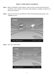
If any other powerline utility is installed, uninstall it and reboot the computer. Step 3 Then click "Setup Utility". 6 When the following image appears, click "200Mbps Device". Step 2 Insert the CD into your computer. Chapter 3: Utility Software Installation Step 1 Before installing the utility software, make sure that no other utility software is installed on your CD-ROM drive.
If any other powerline utility is installed, uninstall it and reboot the computer. Step 3 Then click "Setup Utility". 6 When the following image appears, click "200Mbps Device". Step 2 Insert the CD into your computer. Chapter 3: Utility Software Installation Step 1 Before installing the utility software, make sure that no other utility software is installed on your CD-ROM drive.

User Manual
Page 8
Please click "Apply" to install WinPcap4.1.2. 7 Note : You will get the following image, if your computer did not install WinPcap4.1.2 before.
Please click "Apply" to install WinPcap4.1.2. 7 Note : You will get the following image, if your computer did not install WinPcap4.1.2 before.
User Manual
Page 11
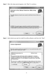
Step 4 When the setup wizard appears, click "Next" to install the utility software, and then click "Next". 10 Step 5 Select where you want to continue.
Step 4 When the setup wizard appears, click "Next" to install the utility software, and then click "Next". 10 Step 5 Select where you want to continue.
User Manual
Page 13
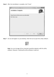
Note: You can manage all the connected powerline adapters with the utility software. However, installing the utility software is complete, click "Close". Click the icon to open the utility software. Step 6 After the installation is optional. 12 Step 7 An icon will appear on your desktop.
Note: You can manage all the connected powerline adapters with the utility software. However, installing the utility software is complete, click "Close". Click the icon to open the utility software. Step 6 After the installation is optional. 12 Step 7 An icon will appear on your desktop.
User Manual
Page 14
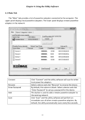
... the existing network. Select a device and click "Enter Password" to the computer. Click "Scan" and the utility software will scan for the device. By default, this column is used to add a remote powerline adapter to rename the device. Chapter 4: Using the Utility Software 4.1 Main Tab The "Main" tab provides a list of other local powerline adapters. This button is blank. The upper panel displays local powerline adapters. By default, the utility automatically...
... the existing network. Select a device and click "Enter Password" to the computer. Click "Scan" and the utility software will scan for the device. By default, this column is used to add a remote powerline adapter to rename the device. Chapter 4: Using the Utility Software 4.1 Main Tab The "Main" tab provides a list of other local powerline adapters. This button is blank. The upper panel displays local powerline adapters. By default, the utility automatically...
User Manual
Page 15
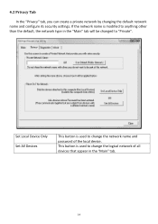
If the network name is modified to anything other than the default, the network type in the "Main" tab. 14 4.2 Privacy Tab In the "Privacy" tab, you can create a private network by changing the default network name and configure its security settings. This button is used to change the logical network of all devices that appear in the "Main" tab will be changed to change the network name and password of the local device. Set Local Device Only Set All Devices This button is used to "Private".
If the network name is modified to anything other than the default, the network type in the "Main" tab. 14 4.2 Privacy Tab In the "Privacy" tab, you can create a private network by changing the default network name and configure its security settings. This button is used to change the logical network of all devices that appear in the "Main" tab will be changed to change the network name and password of the local device. Set Local Device Only Set All Devices This button is used to "Private".

User Manual
Page 16
4.3 Diagnostics Tab The "Diagnostics" tab displays the system information and history of all remote devices. The upper panel displays technical data concerning the software and hardware on the host computer and the lower panel displays the history of all remote devices. 15
4.3 Diagnostics Tab The "Diagnostics" tab displays the system information and history of all remote devices. The upper panel displays technical data concerning the software and hardware on the host computer and the lower panel displays the history of all remote devices. 15

User Manual
Page 17
4.4 About Tab The "About" tab contains some basic information about the software. You can also enable or disable the autoscan function under "Preferences". 16
4.4 About Tab The "About" tab contains some basic information about the software. You can also enable or disable the autoscan function under "Preferences". 16
User Manual
Page 18
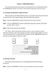
... error occurs, the power LED on the adder will blink evenly at least 3 seconds. 17 This should be done within 1 minute. Step 3 Wait for less than 3 seconds. A PLC B PLC C PLC A and B are connected to the same powerline and you want to add a new device to an existing network, follow the following procedures: Step 1 Press the "NMK(GROUP)" button on the new...
... error occurs, the power LED on the adder will blink evenly at least 3 seconds. 17 This should be done within 1 minute. Step 3 Wait for less than 3 seconds. A PLC B PLC C PLC A and B are connected to the same powerline and you want to add a new device to an existing network, follow the following procedures: Step 1 Press the "NMK(GROUP)" button on the new...
User Manual
Page 19
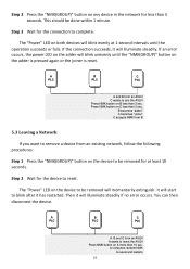
... AVLN A wants to reset. The "Power" LED on the adder is pressed again or the joiner is reset. If the connection succeeds, it will blink unevenly until the operation succeeds or fails. If an error occurs, the power LED on the adder will illuminate steadily. Press NMK button on the device to remove a device from an existing network, follow the following procedures...
... AVLN A wants to reset. The "Power" LED on the adder is pressed again or the joiner is reset. If the connection succeeds, it will blink unevenly until the operation succeeds or fails. If an error occurs, the power LED on the adder will illuminate steadily. Press NMK button on the device to remove a device from an existing network, follow the following procedures...


