
Datasheet
Page 1
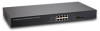
... PoE port. Smart Tools for perfect integration with the most widely used with QoS, and configure link aggregation settings to segregate traffic, prioritize mission‐critical data with different PoE products, such as the total power consumption of establishing a sturdy network environment. Its security and management features include bandwidth control and VLAN (IEEE 802.1Q VLAN tagging and port‐based VLAN). Its standard 19‐inch rack‐mount brackets allow for network...
... PoE port. Smart Tools for perfect integration with the most widely used with QoS, and configure link aggregation settings to segregate traffic, prioritize mission‐critical data with different PoE products, such as the total power consumption of establishing a sturdy network environment. Its security and management features include bandwidth control and VLAN (IEEE 802.1Q VLAN tagging and port‐based VLAN). Its standard 19‐inch rack‐mount brackets allow for network...
Datasheet
Page 2
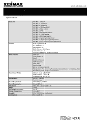
... Spanning tree protocol IEEE 802.1p Class of Service, Priority Protocols RJ‐45 Gigabit Ports: 8 SFP Open Slots: 2 MAC Address: 8K Buffer Memory: 144K Bytes Jumbo Frames: 9.6K Transmission Method: Store and Forward VLAN: 16 Trunk Groups : 4 SNMP Quality of Service IGMP Snooping LACP, RSTP Rate Limiting 802.1x Port‐based Security Management: Port Mirroring, Password‐protected Access, Port Settings, Web‐ base Management, Graphic User Interface 10BaseT Cat. 3, 4, 5 UTP/STP 100BaseTX Cat. 5 UTP/STP 1000BaseT Cat. 5E UTP/STP Per Port: Link...
... Spanning tree protocol IEEE 802.1p Class of Service, Priority Protocols RJ‐45 Gigabit Ports: 8 SFP Open Slots: 2 MAC Address: 8K Buffer Memory: 144K Bytes Jumbo Frames: 9.6K Transmission Method: Store and Forward VLAN: 16 Trunk Groups : 4 SNMP Quality of Service IGMP Snooping LACP, RSTP Rate Limiting 802.1x Port‐based Security Management: Port Mirroring, Password‐protected Access, Port Settings, Web‐ base Management, Graphic User Interface 10BaseT Cat. 3, 4, 5 UTP/STP 100BaseTX Cat. 5 UTP/STP 1000BaseT Cat. 5E UTP/STP Per Port: Link...
Manual
Page 2
... Overview 3 Web Management Feature 3 Specification 4 Mechanical...4 Performance...5 Package Contents 5 Hardware Description 6 Physical Dimensions / Weight 6 Front Panel 6 LED Indicators 6 Rear Panel 7 Hardware Installation 7 Software Description 8 Login...8 Configuration 9 System ...9 System Configuration 9 Ports ...11 Port Configuration 11 Vlan...12 Port Segmentation (VLAN) Configuration 13 Add a Vlan 13 VLAN Configuration List 14 VLAN Setup 14 VLAN Per Port Configuration 14 Aggregation 15 Aggregation / Trunking Configuration 15 LACP...16 LACP Port Configuration 16 RSTP...
... Overview 3 Web Management Feature 3 Specification 4 Mechanical...4 Performance...5 Package Contents 5 Hardware Description 6 Physical Dimensions / Weight 6 Front Panel 6 LED Indicators 6 Rear Panel 7 Hardware Installation 7 Software Description 8 Login...8 Configuration 9 System ...9 System Configuration 9 Ports ...11 Port Configuration 11 Vlan...12 Port Segmentation (VLAN) Configuration 13 Add a Vlan 13 VLAN Configuration List 14 VLAN Setup 14 VLAN Per Port Configuration 14 Aggregation 15 Aggregation / Trunking Configuration 15 LACP...16 LACP Port Configuration 16 RSTP...
Manual
Page 4
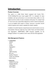
moreover, it provides smooth network migration and is specifically designed for small to upgrade the network capacity. Web Management Features ¾ Configuration System Ports VLANs Aggregation LACP RSTP IGMP Snooping Mirroring Quality of Service Power over Ethernet (PoE), Link Aggregation, SNMP/RMON, IGMP Snooping capability via the intelligent software. The compact rigid 19" rack-mount size is easy to medium workgroups. It is designed for both metro-LAN and office application. It can be installed where space is suitable...
moreover, it provides smooth network migration and is specifically designed for small to upgrade the network capacity. Web Management Features ¾ Configuration System Ports VLANs Aggregation LACP RSTP IGMP Snooping Mirroring Quality of Service Power over Ethernet (PoE), Link Aggregation, SNMP/RMON, IGMP Snooping capability via the intelligent software. The compact rigid 19" rack-mount size is easy to medium workgroups. It is designed for both metro-LAN and office application. It can be installed where space is suitable...

Manual
Page 5
... Restart Factory Default Software Upload Configuration File Transfer Logout Specifications ¾ Standard IEEE 802.3 10BaseT IEEE 802.3u 100BaseTX IEEE 802.3ab 1000BaseT IEEE 802.3z 1000BaseSX/LX IEEE 802.3x Full-duplex Flow Control IEEE 802.3ad Link Aggregation IEEE 802.1Q VLAN IEEE 802.1d Spanning tree protocol IEEE 802.1w Rapid Spanning tree protocol IEEE 802.1p QoS IEEE 802.3af- 2003 Power over Ethernet IEEE...
... Restart Factory Default Software Upload Configuration File Transfer Logout Specifications ¾ Standard IEEE 802.3 10BaseT IEEE 802.3u 100BaseTX IEEE 802.3ab 1000BaseT IEEE 802.3z 1000BaseSX/LX IEEE 802.3x Full-duplex Flow Control IEEE 802.3ad Link Aggregation IEEE 802.1Q VLAN IEEE 802.1d Spanning tree protocol IEEE 802.1w Rapid Spanning tree protocol IEEE 802.1p QoS IEEE 802.3af- 2003 Power over Ethernet IEEE...

Manual
Page 9
At the first, open the web browser, and go to understand the procedure. The login process is completed and comes out the sign "Password successfully entered". Login Password: 1234 Figure 1-1 After the user login, the right side of website shows all functions as Fig. 1-2. 8 Please follow the description to 192.168.2.1 site then the user will see the login screen. Key in the password to set up and manage the switch through the web user interface. Software Description This part instructs user how to pass the authentication then clicks the Apply.
At the first, open the web browser, and go to understand the procedure. The login process is completed and comes out the sign "Password successfully entered". Login Password: 1234 Figure 1-1 After the user login, the right side of website shows all functions as Fig. 1-2. 8 Please follow the description to 192.168.2.1 site then the user will see the login screen. Key in the password to set up and manage the switch through the web user interface. Software Description This part instructs user how to pass the authentication then clicks the Apply.
Manual
Page 11
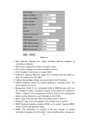
... new user name (The default value is 'admin'). ¾ Password: Type in the new password (The default value is using. Figure 1-3 ¾ MAC Address: Displays the unique hardware address assigned by manufacturer (default). ¾ S/W Version: Displays the switch's firmware version. ¾ H/W Version: Displays the switch's Hardware version. ¾ DHCP Enabled: Click the box to enable DHCP ¾ Fallback IP address: Manually assign the IP address that the network is 'admin'). ¾ SNMP Enabled: Enables or disables SNMP on the switch are 10 However, if the management VLAN is changed...
... new user name (The default value is 'admin'). ¾ Password: Type in the new password (The default value is using. Figure 1-3 ¾ MAC Address: Displays the unique hardware address assigned by manufacturer (default). ¾ S/W Version: Displays the switch's firmware version. ¾ H/W Version: Displays the switch's Hardware version. ¾ DHCP Enabled: Click the box to enable DHCP ¾ Fallback IP address: Manually assign the IP address that the network is 'admin'). ¾ SNMP Enabled: Enables or disables SNMP on the switch are 10 However, if the management VLAN is changed...
Manual
Page 12
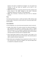
...; Power Saving Mode: Adjusts the power provided to ports based on MAC address, limits the total number of the cable used to connect to other devices. Authorized management stations are reported by the switch to specified trap managers. Only sufficient power is used to maintain connection requirements. ¾ Mode: allow user to manually set and view the operation mode for each port. ¾ Enable Jumbo Frames: This switch provides more efficient throughput for large sequential data transfers by supporting jumbo frames on Gigabit Ethernet ports...
...; Power Saving Mode: Adjusts the power provided to ports based on MAC address, limits the total number of the cable used to connect to other devices. Authorized management stations are reported by the switch to specified trap managers. Only sufficient power is used to maintain connection requirements. ¾ Mode: allow user to manually set and view the operation mode for each port. ¾ Enable Jumbo Frames: This switch provides more efficient throughput for large sequential data transfers by supporting jumbo frames on Gigabit Ethernet ports...
Manual
Page 14
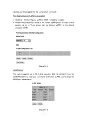
Figure 1-5-2 13 VLAN 1 is the default untagged VLAN. Figure 1-5-1 VLAN Setup The switch supports up to 16 VLAN groups can create and delete VLANs, and change the VLAN port membership. devices are still plugged into the same switch physically. From the VLAN Membership page you can be defined. Up to 16 VLANs based on 802.1Q standard. Port Segmentation (VLAN) Configuration ¾ VLAN ID: ID of configured VLAN (1-4096, no leading zeroes). ¾ VLAN Configuration List: Lists all the current VLAN groups created for this system.
Figure 1-5-2 13 VLAN 1 is the default untagged VLAN. Figure 1-5-1 VLAN Setup The switch supports up to 16 VLAN groups can create and delete VLANs, and change the VLAN port membership. devices are still plugged into the same switch physically. From the VLAN Membership page you can be defined. Up to 16 VLANs based on 802.1Q standard. Port Segmentation (VLAN) Configuration ¾ VLAN ID: ID of configured VLAN (1-4096, no leading zeroes). ¾ VLAN Configuration List: Lists all the current VLAN groups created for this system.
Manual
Page 15
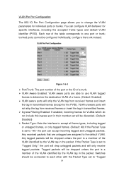
... the tag in the packet. trunked ports cannot be connected to each other with the Packet Type set to "Tagged 14 If the Packet Type is set to "All," the port can configure VLAN behavior for VLANs which do not include this ingress port in transmitted frames. ¾ Ingress Filtering Enabled: If enabled, incoming frames for specific interfaces, including the accepted frame types and default VLAN identifier (PVID). configure the trunk instead. VLAN unaware ports will be dropped unless...
... the tag in the packet. trunked ports cannot be connected to each other with the Packet Type set to "Tagged 14 If the Packet Type is set to "All," the port can configure VLAN behavior for VLANs which do not include this ingress port in transmitted frames. ¾ Ingress Filtering Enabled: If enabled, incoming frames for specific interfaces, including the accepted frame types and default VLAN identifier (PVID). configure the trunk instead. VLAN unaware ports will be dropped unless...
Manual
Page 16
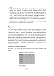
... to untagged frames received on ports that called a hash algorithm. Only." ¾ PVID: The PVID (Port VLAN ID) is set to "Tagged Only." (Default PVID: 1) It is the same as the standard configuration. When the PVID is associated with untagged, ingress packets. A port failure within the trunk in the trunk. Figure 1-6 15 Aggregation Port trunk allows multiple links to be directed to service. Traffic in a switched inter-network. It provides...
... to untagged frames received on ports that called a hash algorithm. Only." ¾ PVID: The PVID (Port VLAN ID) is set to "Tagged Only." (Default PVID: 1) It is the same as the standard configuration. When the PVID is associated with untagged, ingress packets. A port failure within the trunk in the trunk. Figure 1-6 15 Aggregation Port trunk allows multiple links to be directed to service. Traffic in a switched inter-network. It provides...
Manual
Page 17
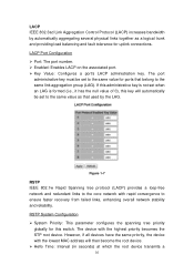
... configures the spanning tree priority globally for uplink connections. However, if all devices have the same priority, the device with the lowest MAC address will automatically be set when an LAG is not set to the same value for ports that used by automatically aggregating several physical links together as that belong to ensure faster recovery from failed links, enhancing overall network stability and reliability. LACP IEEE 802.3ad Link Aggregation Control...
... configures the spanning tree priority globally for uplink connections. However, if all devices have the same priority, the device with the lowest MAC address will automatically be set when an LAG is not set to the same value for ports that used by automatically aggregating several physical links together as that belong to ensure faster recovery from failed links, enhancing overall network stability and reliability. LACP IEEE 802.3ad Link Aggregation Control...
Manual
Page 20
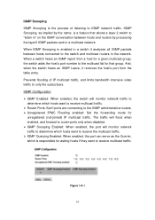
... IPMC Flooding enabled: Set the forwarding mode for that allows a layer 2 switch to "listen in" on the IGMP conversation between hosts connected to the multicast list for unregistered (not-joined) IP multicast traffic. The traffic will flood when enabled, and forward to router-ports only when disabled. ¾ IGMP Snooping Enabled: When enabled, the port will monitor network traffic to determine which is responsible for a given multicast group, the switch adds the host's port number to the switch and multicast routers in a multicast network. When IGMP Snooping is...
... IPMC Flooding enabled: Set the forwarding mode for that allows a layer 2 switch to "listen in" on the IGMP conversation between hosts connected to the multicast list for unregistered (not-joined) IP multicast traffic. The traffic will flood when enabled, and forward to router-ports only when disabled. ¾ IGMP Snooping Enabled: When enabled, the port will monitor network traffic to determine which is responsible for a given multicast group, the switch adds the host's port number to the switch and multicast routers in a multicast network. When IGMP Snooping is...
Manual
Page 21
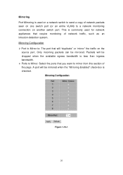
... one switch port (or an entire VLAN) to a network monitoring connection on the source port. A port will be dropped when the available egress bandwidth is less than ingress bandwidth. ¾ Ports to Mirror: Select the ports that require monitoring of the page. Only incoming packets can be mirrored when the "Mirroring Enabled" check-box is checked. Mirroring Port Mirroring is used for network appliances that you want to mirror from this section of network traffic, such...
... one switch port (or an entire VLAN) to a network monitoring connection on the source port. A port will be dropped when the available egress bandwidth is less than ingress bandwidth. ¾ Ports to Mirror: Select the ports that require monitoring of the page. Only incoming packets can be mirrored when the "Mirroring Enabled" check-box is checked. Mirroring Port Mirroring is used for network appliances that you want to mirror from this section of network traffic, such...
Manual
Page 24
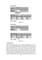
When QoS Mode is set the values in the range 0 - 63. The six bits allow the DSCP field to quickly set to DSCP, the DSCP Configuration table is contained within an IP (TCP or UDP) header. The default settings map all DSCP values to a hardware output queue (low, normal, medium or high). The Differentiated Services Code Point (DSCP) is a six-bit field that...
When QoS Mode is set the values in the range 0 - 63. The six bits allow the DSCP field to quickly set to DSCP, the DSCP Configuration table is contained within an IP (TCP or UDP) header. The default settings map all DSCP values to a hardware output queue (low, normal, medium or high). The Differentiated Services Code Point (DSCP) is a six-bit field that...
Manual
Page 26
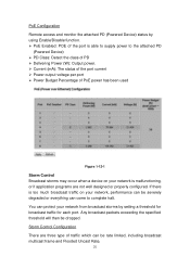
...): The status of the port current ¾ Power output voltage per port ¾ Power Budget Percentage of PoE power has been used Figure 1-12-1 Storm Control Broadcast storms may occur when a device on your network is malfunctioning, or if application programs are three type of the port is able to supply power to complete halt. PoE Configuration Remote access and monitor the attached PD (Powered Device) status by setting a threshold for broadcast traffic for each port.
...): The status of the port current ¾ Power output voltage per port ¾ Power Budget Percentage of PoE power has been used Figure 1-12-1 Storm Control Broadcast storms may occur when a device on your network is malfunctioning, or if application programs are three type of the port is able to supply power to complete halt. PoE Configuration Remote access and monitor the attached PD (Powered Device) status by setting a threshold for broadcast traffic for each port.
Manual
Page 29
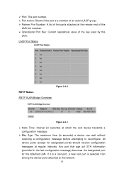
... time (in the last configuration message) becomes the designated port for designated ports) should receive configuration messages at the remote end of this LAG link member. ¾ Operational Port Key: Current operational value of the key used by this LAG. All device ports (except for the attached LAN. If it is a root port, a new root port is a member of an active LACP group. ¾ Partner Port Number: A list of the ports...
... time (in the last configuration message) becomes the designated port for designated ports) should receive configuration messages at the remote end of this LAG link member. ¾ Operational Port Key: Current operational value of the key used by this LAG. All device ports (except for the attached LAN. If it is a root port, a new root port is a member of an active LACP group. ¾ Partner Port Number: A list of the ports...
Manual
Page 30
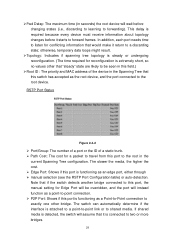
... the RSTP Port Configuration table) or auto-detection. Note that if the switch detects another bridge connected to this port, the manual setting for a packet to travel from this port is extremely short, so no values other bridge. This delay is functioning as a point-to-point connection. ¾ P2P Port: Shows if this port to a discarding state; RSTP Port Status Figure 2-4-2 ¾ Port/Group: The number of a port or...
... the RSTP Port Configuration table) or auto-detection. Note that if the switch detects another bridge connected to this port, the manual setting for a packet to travel from this port is extremely short, so no values other bridge. This delay is functioning as a point-to-point connection. ¾ P2P Port: Shows if this port to a discarding state; RSTP Port Status Figure 2-4-2 ¾ Port/Group: The number of a port or...
Manual
Page 36
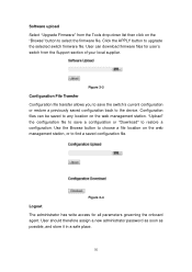
Use the Browse button to choose a file location on the web management station, or to upgrade the selected switch firmware file. Software upload Select "Upgrade Firmware" from the Support section of your local supplier. Figure 3-3 Configuration File Transfer Configuration file transfer allows you to save a configuration or "Download" to select the firmware file. Configuration files can download firmware files for all parameters governing the onboard agent. User can be saved to the device. Click the APPLY button to find a saved configuration file. Figure 3-4 Logout...
Use the Browse button to choose a file location on the web management station, or to upgrade the selected switch firmware file. Software upload Select "Upgrade Firmware" from the Support section of your local supplier. Figure 3-3 Configuration File Transfer Configuration file transfer allows you to save a configuration or "Download" to select the firmware file. Configuration files can download firmware files for all parameters governing the onboard agent. User can be saved to the device. Click the APPLY button to find a saved configuration file. Figure 3-4 Logout...

Manual
Page 37
Reset button for the factory default setting Please take the following steps to reset the Web Smart Switch back to the original default: Step 1: Turn on the Web Smart Switch Step 2: Press and hold the reset button continuously for 20 seconds and the configuration of switch will back to the default setting. 36 Step 3: The switch will reboot for 5 seconds and release the reset button.
Reset button for the factory default setting Please take the following steps to reset the Web Smart Switch back to the original default: Step 1: Turn on the Web Smart Switch Step 2: Press and hold the reset button continuously for 20 seconds and the configuration of switch will back to the default setting. 36 Step 3: The switch will reboot for 5 seconds and release the reset button.


