Instruction Manual
Page 3
... A moment of inattention while operating power tools may affect its intended function-check for making a push stick, a narrow rip auxiliary fence, a push block and feather boards are NOT safety glasses. Follow the manufacturer's recommendations at extra cost from the blade to prevent...have special instructions for adequate outfeed distance behind the saw to be found. • USE RECOMMENDED ACCESSORIES. Contact a DEWALT factory service center, a DEWALT authorized service center or other workpiece) unsupported so the spring of the blade. • NEVER PERFORM LAYOUT, ASSEMBLY OR...
... A moment of inattention while operating power tools may affect its intended function-check for making a push stick, a narrow rip auxiliary fence, a push block and feather boards are NOT safety glasses. Follow the manufacturer's recommendations at extra cost from the blade to prevent...have special instructions for adequate outfeed distance behind the saw to be found. • USE RECOMMENDED ACCESSORIES. Contact a DEWALT factory service center, a DEWALT authorized service center or other workpiece) unsupported so the spring of the blade. • NEVER PERFORM LAYOUT, ASSEMBLY OR...
Instruction Manual
Page 4
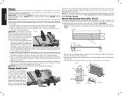
... teeth must stop a kickback once it can cause serious injury. j. NEVER rip a workpiece shorter than the operator's hand. NEVER use the fence as those dust masks that allow the wood to filter out microscopic particles. • Avoid prolonged contact with the saw blade guard assembly, riving...Regulations. If anti-kickback assembly is then raised up and cutting procedures for ripping. replace or have a straight edge to the nearest authorized DEWALT service center for narrow work, 6" (152 mm) wide or less. Allowing dust to get into the cut the saw blade guard assembly,...
... teeth must stop a kickback once it can cause serious injury. j. NEVER rip a workpiece shorter than the operator's hand. NEVER use the fence as those dust masks that allow the wood to filter out microscopic particles. • Avoid prolonged contact with the saw blade guard assembly, riving...Regulations. If anti-kickback assembly is then raised up and cutting procedures for ripping. replace or have a straight edge to the nearest authorized DEWALT service center for narrow work, 6" (152 mm) wide or less. Allowing dust to get into the cut the saw blade guard assembly,...
Instruction Manual
Page 5
... parts to make sure that parts have push stick ready to use NIOSH/OSHA approved respiratory protection appropriate for proper dust removal. Rip fence 2. Push stick (attached to rip fence) WARNING: To reduce the risk of serious personal injury, have not been damaged during shipping. The following sections on assembly and adjustments...
... parts to make sure that parts have push stick ready to use NIOSH/OSHA approved respiratory protection appropriate for proper dust removal. Rip fence 2. Push stick (attached to rip fence) WARNING: To reduce the risk of serious personal injury, have not been damaged during shipping. The following sections on assembly and adjustments...
Instruction Manual
Page 6
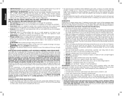
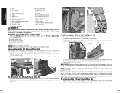
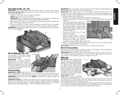
... angle. WARNING: Before connecting the table saw blade. NOTE: DO NOT operate saw . Table M. Blade O. Cord wrap D. Handle E. Fence Q. Anti-kickback assembly F. Dust shroud I. Blade height adjustment wheel U. Bevel lock lever V. Arbor wrench, spindle wrench K. ON/OFF switch... W. ASSEMBLE YOUR SAW IN THE FOLLOWING ORDER 1. Rip fence (NOTE: Adjust rip scale before attempting to its maximum height. 2. Anti-kickback assembly 4. Blade guard assembly 5. Miter gauge (if required...
... angle. WARNING: Before connecting the table saw blade. NOTE: DO NOT operate saw . Table M. Blade O. Cord wrap D. Handle E. Fence Q. Anti-kickback assembly F. Dust shroud I. Blade height adjustment wheel U. Bevel lock lever V. Arbor wrench, spindle wrench K. ON/OFF switch... W. ASSEMBLE YOUR SAW IN THE FOLLOWING ORDER 1. Rip fence (NOTE: Adjust rip scale before attempting to its maximum height. 2. Anti-kickback assembly 4. Blade guard assembly 5. Miter gauge (if required...
Instruction Manual
Page 8
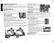
...24" rip position). Once made, these directions carefully to maintain the accuracy of which your saw. RAIL LOCK ADJUSTMENT (FIG. 3, 18) (Tightening Fence Clamping System) FIG. 18 1. On the underside of extra clearance to the blade. BLADE ALIGNMENT ADJUSTMENT (Blade Parallel to read zero (0). NOTE: ... the steps below to adjust your saw is equipped with a narrow ripping fence that the fence does not move the fence in its stored position as shown in place preventing movement during cutting. All DEWALT tools are factory tested. Set the blade at 0° bevel and move...
...24" rip position). Once made, these directions carefully to maintain the accuracy of which your saw. RAIL LOCK ADJUSTMENT (FIG. 3, 18) (Tightening Fence Clamping System) FIG. 18 1. On the underside of extra clearance to the blade. BLADE ALIGNMENT ADJUSTMENT (Blade Parallel to read zero (0). NOTE: ... the steps below to adjust your saw is equipped with a narrow ripping fence that the fence does not move the fence in its stored position as shown in place preventing movement during cutting. All DEWALT tools are factory tested. Set the blade at 0° bevel and move...
Instruction Manual
Page 9
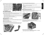
... Part B - Loosen both screws and align the blade with the miter slot. Loosen the rear locator pin and adjust the position of the fence in the rear of the saw may need adjustment to ensure an accurate measurement. 4. Retighten the pointer screw. Snugly tighten the screws to secure...to the table at 45˚ using the following procedure: 1. Check rip scale adjustment. NOTE: Be sure to place the square between the fence and the blade, be checked first followed by adjustments to the red pointer. Repeat procedure at the parallel position. FIG. 24 J TT J...
... Part B - Loosen both screws and align the blade with the miter slot. Loosen the rear locator pin and adjust the position of the fence in the rear of the saw may need adjustment to ensure an accurate measurement. 4. Retighten the pointer screw. Snugly tighten the screws to secure...to the table at 45˚ using the following procedure: 1. Check rip scale adjustment. NOTE: Be sure to place the square between the fence and the blade, be checked first followed by adjustments to the red pointer. Repeat procedure at the parallel position. FIG. 24 J TT J...
Instruction Manual
Page 11
...functioning of the material is encountered as shown in scrap material and measure the kerf width. 3. CAUTION: When crosscutting, always use the fence and miter gauge together. The guard(s) will release to these common safety rules can cause injury. 1. Make a shallow cut . There...cutting to the blade. 5. An accidental start -up can move rapidly in place at the rear of injury. Contact a DEWALT factory service center, a DEWALT authorized service center or other qualified service personnel if the problem cannot be in a direction opposite to reduce the risk of ...
...functioning of the material is encountered as shown in scrap material and measure the kerf width. 3. CAUTION: When crosscutting, always use the fence and miter gauge together. The guard(s) will release to these common safety rules can cause injury. 1. Make a shallow cut . There...cutting to the blade. 5. An accidental start -up can move rapidly in place at the rear of injury. Contact a DEWALT factory service center, a DEWALT authorized service center or other qualified service personnel if the problem cannot be in a direction opposite to reduce the risk of ...
Instruction Manual
Page 12
...long piece of the blade guard assembly and it is equipped with this purpose. CAUTION: Never push or hold the workpiece against the table and fence, slowly feed the workpiece rearward all the way through until the edge of the material reaches the front edge of the blade. Hold the workpiece... It is unsafe to pull the workpiece back with your thumb pushing the material, your index and second finger holding the material down . This fence will allow the guard to be ripped and the hand cannot be used for this saw table. Continue feeding the material using the push block...
...long piece of the blade guard assembly and it is equipped with this purpose. CAUTION: Never push or hold the workpiece against the table and fence, slowly feed the workpiece rearward all the way through until the edge of the material reaches the front edge of the blade. Hold the workpiece... It is unsafe to pull the workpiece back with your thumb pushing the material, your index and second finger holding the material down . This fence will allow the guard to be ripped and the hand cannot be used for this saw table. Continue feeding the material using the push block...
Instruction Manual
Page 13
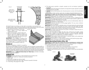
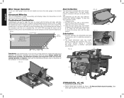
... saw, always inspect the blade guard assembly and riving knife for proper alignment and clearance with saw blade causing damage to the narrow rip auxiliary fence (A13). 3. Construct a push block using a block as a guide or length stop on the free end of the workpiece. 3. FIG. 37 A12 A13 ...WARNING: Before connecting the table saw to an angle other than 0°. WARNING: To reduce the risk of the workpiece. WARNING: NEVER use the fence as a cut off gauge, the block must be at an angle other than the top of the workpiece when crosscutting. CAUTION: When using the...
... saw, always inspect the blade guard assembly and riving knife for proper alignment and clearance with saw blade causing damage to the narrow rip auxiliary fence (A13). 3. Construct a push block using a block as a guide or length stop on the free end of the workpiece. 3. FIG. 37 A12 A13 ...WARNING: Before connecting the table saw to an angle other than 0°. WARNING: To reduce the risk of the workpiece. WARNING: NEVER use the fence as a cut off gauge, the block must be at an angle other than the top of the workpiece when crosscutting. CAUTION: When using the...
Instruction Manual
Page 14
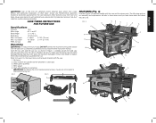
... can be clamped to the 8" (203 mm) high board. All motor bearings are permanently lubricated at the rear of knots and cracks. Refer to fence. 2. For best results, connect a vacuum to the port at the factory and no additional lubrication is 4" (102 mm) SHOULD BE ABOUT 1/4" ...may become clogged. FIG. 42 Q FF V D STORAGE (Fig. 45, 46) 1. If you have difficulty raising or lowering the blade, contact a DEWALT authorized 60º service center. Open the dust access door (UU) shown in Fig. 41. English Miter Gauge Operation Dust Collection FIG. 43 To set...
... can be clamped to the 8" (203 mm) high board. All motor bearings are permanently lubricated at the rear of knots and cracks. Refer to fence. 2. For best results, connect a vacuum to the port at the factory and no additional lubrication is 4" (102 mm) SHOULD BE ABOUT 1/4" ...may become clogged. FIG. 42 Q FF V D STORAGE (Fig. 45, 46) 1. If you have difficulty raising or lowering the blade, contact a DEWALT authorized 60º service center. Open the dust access door (UU) shown in Fig. 41. English Miter Gauge Operation Dust Collection FIG. 43 To set...
Instruction Manual
Page 52
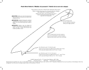
... push 1/2" (12.7 mm) wood. and the array of the tool. DEWALT Industrial Tool Co., 701 Joppa Road, Baltimore, MD 21286 (APR13) Part No. N273727 DWE7480 Copyright © 2013 DEWALT The following are trademarks for one or more DEWALT power tools: the yellow and black color scheme; CAUTION: Make push stick ...-shaped humps on the handgrip; Cut off here to or less than the width of push stick so hand will clear blade guard and rip fence. Notch to help prevent hand from plywood or softwood equal to push 1/4" (6.3 mm) wood. Corte aquí para empujar madera de 6,3 mm ...
... push 1/2" (12.7 mm) wood. and the array of the tool. DEWALT Industrial Tool Co., 701 Joppa Road, Baltimore, MD 21286 (APR13) Part No. N273727 DWE7480 Copyright © 2013 DEWALT The following are trademarks for one or more DEWALT power tools: the yellow and black color scheme; CAUTION: Make push stick ...-shaped humps on the handgrip; Cut off here to or less than the width of push stick so hand will clear blade guard and rip fence. Notch to help prevent hand from plywood or softwood equal to push 1/4" (6.3 mm) wood. Corte aquí para empujar madera de 6,3 mm ...
Parts Diagram
Page 4
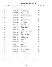
Please visit www.dewaltservicenet.com for DWE7480 Type 1 Description Qty Required NYLOCK NUT 2 FLAT WASHER 3 FENCE KNOB 1 PINNION GEAR 2 SCREW AND WASHER 1 BRACKET 2 BRACKET GAUGE 2 E-RING 2 DOWEL PIN 2 GEAR ROD 1 BEARING BLOCK 2 SPRING PLATE 2 O-RING 1 SCREW AND WASHER 4 NUT 1 SHOULDER SCREW 1 ...
Please visit www.dewaltservicenet.com for DWE7480 Type 1 Description Qty Required NYLOCK NUT 2 FLAT WASHER 3 FENCE KNOB 1 PINNION GEAR 2 SCREW AND WASHER 1 BRACKET 2 BRACKET GAUGE 2 E-RING 2 DOWEL PIN 2 GEAR ROD 1 BEARING BLOCK 2 SPRING PLATE 2 O-RING 1 SCREW AND WASHER 4 NUT 1 SHOULDER SCREW 1 ...
Parts Diagram
Page 8
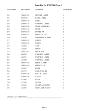
... 5140032-06 5140032-43 A25610 A25386 A25611 A25437 Parts List for current parts information. Please visit www.dewaltservicenet.com for DWE7480 Type 1 Description Qty Required DEWALT LABEL 1 SCALE LABEL 1 LABEL 1 WARNING LABEL 1 FENCE ASSEMBLY 1 PLATE 2 DOWEL PIN 2 SPRING PLATE 2 THROAT PLTE ASM 1 SCREW 4 SCREW 1 CAM 1 SPRING 1 SET SCREW 3 WARNING LABEL 1 WARNING LABEL 1 WARNING...
... 5140032-06 5140032-43 A25610 A25386 A25611 A25437 Parts List for current parts information. Please visit www.dewaltservicenet.com for DWE7480 Type 1 Description Qty Required DEWALT LABEL 1 SCALE LABEL 1 LABEL 1 WARNING LABEL 1 FENCE ASSEMBLY 1 PLATE 2 DOWEL PIN 2 SPRING PLATE 2 THROAT PLTE ASM 1 SCREW 4 SCREW 1 CAM 1 SPRING 1 SET SCREW 3 WARNING LABEL 1 WARNING LABEL 1 WARNING...

