
Instruction Manual
Page 3
...Do not use an extension cord suitable for carrying, pulling or unplugging the power tool. Keep cord away from heat, oil, sharp edges or moving parts. e) When operating a power tool outdoors, use any way. Use of a cord suitable for each signal word. WARNING: Indicates a potentially hazardous situation... of electric shock. Please read the instruction manual. IF YOU HAVE ANY QUESTIONS OR COMMENTS ABOUT THIS OR ANY DEWALT TOOL, CALL US TOLL FREE AT: 1-800-4-DEWALT (1-800-433-9258). Unmodified plugs and matching outlets will increase the risk of electric shock if your mains-operated ...
...Do not use an extension cord suitable for carrying, pulling or unplugging the power tool. Keep cord away from heat, oil, sharp edges or moving parts. e) When operating a power tool outdoors, use any way. Use of a cord suitable for each signal word. WARNING: Indicates a potentially hazardous situation... of electric shock. Please read the instruction manual. IF YOU HAVE ANY QUESTIONS OR COMMENTS ABOUT THIS OR ANY DEWALT TOOL, CALL US TOLL FREE AT: 1-800-4-DEWALT (1-800-433-9258). Unmodified plugs and matching outlets will increase the risk of electric shock if your mains-operated ...
Instruction Manual
Page 4
... making any adjustments, changing accessories, or storing power tools. Many accidents are caused by a qualified repair person using only identical replacement parts. f) Keep cutting tools sharp and clean. Carrying power tools with the power tool or these instructions to power source and/ or ...result in accordance with the switch is maintained. 2 Properly maintained cutting tools with sharp cutting edges are less likely to a rotating part of parts and any adjusting key or wrench before use common sense when operating a power tool. in serious personal injury. Do not use a...
... making any adjustments, changing accessories, or storing power tools. Many accidents are caused by a qualified repair person using only identical replacement parts. f) Keep cutting tools sharp and clean. Carrying power tools with the power tool or these instructions to power source and/ or ...result in accordance with the switch is maintained. 2 Properly maintained cutting tools with sharp cutting edges are less likely to a rotating part of parts and any adjusting key or wrench before use common sense when operating a power tool. in serious personal injury. Do not use a...

Instruction Manual
Page 5
... rated speed of the accessory must be capable of accessories must fit the locating diameter of the power tool "live " wire may make exposed metal parts of the flange. e) Threaded mounting of stopping flying debris generated by flanges, the arbor hole of the accessory must match the grinder spindle thread. Accessories...
... rated speed of the accessory must be capable of accessories must fit the locating diameter of the power tool "live " wire may make exposed metal parts of the flange. e) Threaded mounting of stopping flying debris generated by flanges, the arbor hole of the accessory must match the grinder spindle thread. Accessories...
Instruction Manual
Page 6
... be caught in injury. Sparks could snag your body. Using inappropriate accessories can be detected. Loose clothes, jewelry or long hair can result in moving parts and should always be pulled into your clothing, pulling the accessory into the spinning accessory. The wheel may cause electrical hazards. k) Never lay the power...'s rotation at all times. Never start the tool with a person in turn causes the uncontrolled power tool to a stable platform. x) Air vents often cover moving parts. If you lose control, the cord may be forced in a careful manner.
... be caught in injury. Sparks could snag your body. Using inappropriate accessories can be detected. Loose clothes, jewelry or long hair can result in moving parts and should always be pulled into your clothing, pulling the accessory into the spinning accessory. The wheel may cause electrical hazards. k) Never lay the power...'s rotation at all times. Never start the tool with a person in turn causes the uncontrolled power tool to a stable platform. x) Air vents often cover moving parts. If you lose control, the cord may be forced in a careful manner.

Instruction Manual
Page 10
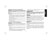
... Type 27 Guard (4-1/2" / 115mm) C. Lock-off lever J. A. Threaded locking flange I G D H F Lock-on button E. Spindle (DWE402, DWE402G) F. Damage or personal injury could result. Spindle lock button K. Guard release lever D. Paddle switch G. Side handle FIG. 1 J E J 8 DWE402, DWE402N, DWE402G K I C A DWE4214 B I . Slider switch (DWE4214) H. English Minimum Gauge for Cord Sets Volts Total Length of ... 16 14 12 Not Recommended SAVE THESE INSTRUCTIONS FOR FUTURE USE COMPONENTS (Fig. 1) WARNING: Never modify the power tool or any part of it.
... Type 27 Guard (4-1/2" / 115mm) C. Lock-off lever J. A. Threaded locking flange I G D H F Lock-on button E. Spindle (DWE402, DWE402G) F. Damage or personal injury could result. Spindle lock button K. Guard release lever D. Paddle switch G. Side handle FIG. 1 J E J 8 DWE402, DWE402N, DWE402G K I C A DWE4214 B I . Slider switch (DWE4214) H. English Minimum Gauge for Cord Sets Volts Total Length of ... 16 14 12 Not Recommended SAVE THESE INSTRUCTIONS FOR FUTURE USE COMPONENTS (Fig. 1) WARNING: Never modify the power tool or any part of it.

Instruction Manual
Page 14
... connecting the tool to a power source depress and release the paddle switch (A) once [DWE402: without depressing the lock-on , push the lock-off FIG. 4 lever (C) toward... -up to full speed before touching the work surface. Turn the tool off position by pressing the rear part of the switch and releasing. SLIDER SWITCH (FIG. 5) DWE4214 CAUTION: Before connecting the tool to a power...it is reconnected. NOTE: To reduce unexpected tool movement, do not switch the tool on the rear most part of the switch. Allow the tool to stop the tool, release the ON/OFF switch. 12 English ...
... connecting the tool to a power source depress and release the paddle switch (A) once [DWE402: without depressing the lock-on , push the lock-off FIG. 4 lever (C) toward... -up to full speed before touching the work surface. Turn the tool off position by pressing the rear part of the switch and releasing. SLIDER SWITCH (FIG. 5) DWE4214 CAUTION: Before connecting the tool to a power...it is reconnected. NOTE: To reduce unexpected tool movement, do not switch the tool on the rear most part of the switch. Allow the tool to stop the tool, release the ON/OFF switch. 12 English ...

Instruction Manual
Page 15
...C A K will result and attached accessory may spin off , the tool is D turned off possibly resulting in continuous mode, press the rear part of the switch and release. With the tool running, depress the lock-on spindle (E) with included flanges. To unlock the tool, depress and release... manual. CAUTION: Allow the tool to reach full speed before touching tool to rotate the spindle further. FIG. 5 LOCK-ON BUTTON (FIG. 6) B DWE402, DWE402G The lock-on , push the lock-off . To lock the tool on button (K) offers FIG. 6 increased comfort in this manual for more ...
...C A K will result and attached accessory may spin off , the tool is D turned off possibly resulting in continuous mode, press the rear part of the switch and release. With the tool running, depress the lock-on spindle (E) with included flanges. To unlock the tool, depress and release... manual. CAUTION: Allow the tool to reach full speed before touching tool to rotate the spindle further. FIG. 5 LOCK-ON BUTTON (FIG. 6) B DWE402, DWE402G The lock-on , push the lock-off . To lock the tool on button (K) offers FIG. 6 increased comfort in this manual for more ...
Instruction Manual
Page 21
...into a liquid. 5. Once a cut . Changing the angle will be used for side injury, only DEWALT recommended accessories should be against the wheel when the wheel is established in locating any part of injury, turn the tool to operate Industrial Tool Co., 701 East Joppa Road, Baltimore, MD 21286..., at 1. at call 1-800-4-DEWALT (1-800-433-9258) or visit our website: www. raised section (pilot...
...into a liquid. 5. Once a cut . Changing the angle will be used for side injury, only DEWALT recommended accessories should be against the wheel when the wheel is established in locating any part of injury, turn the tool to operate Industrial Tool Co., 701 East Joppa Road, Baltimore, MD 21286..., at 1. at call 1-800-4-DEWALT (1-800-433-9258) or visit our website: www. raised section (pilot...

Instruction Manual
Page 22
... theft, your registration of purchase. Register online at www.dewalt.com/register. Three Year Limited Warranty DEWALT will maintain the tool and replace worn parts caused by normal use identical replacement parts. This warranty does not apply to the warranty, DEWALT tools are missing, call 1-800-4-DEWALT (1-800433-9258). In addition to accessories or damage caused...
... theft, your registration of purchase. Register online at www.dewalt.com/register. Three Year Limited Warranty DEWALT will maintain the tool and replace worn parts caused by normal use identical replacement parts. This warranty does not apply to the warranty, DEWALT tools are missing, call 1-800-4-DEWALT (1-800433-9258). In addition to accessories or damage caused...

Instruction Manual
Page 72
the kit box configuration; N382909 DWE402, DWE402N, DWE402G, DWE4214 Copyright © 2014 DEWALT The following are trademarks for one or more DEWALT power tools: the yellow and black color scheme; the "D" shaped air intake grill; and the array of lozenge-shaped humps on the surface of pyramids on the handgrip; the array of the tool. DEWALT Industrial Tool Co., 701 East Joppa Road, Baltimore, MD 21286 (SEP14) Part No.
the kit box configuration; N382909 DWE402, DWE402N, DWE402G, DWE4214 Copyright © 2014 DEWALT The following are trademarks for one or more DEWALT power tools: the yellow and black color scheme; the "D" shaped air intake grill; and the array of lozenge-shaped humps on the surface of pyramids on the handgrip; the array of the tool. DEWALT Industrial Tool Co., 701 East Joppa Road, Baltimore, MD 21286 (SEP14) Part No.

