Literature/Product Sheet
Page 1
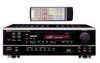
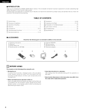
... remote control. The Signal Level Divided Construction (SLDC) chassis, developed by DENON, is a high-quality stereo receiver that combines real versatility with volume level adjustment via remote control, are faithfully amplified and transmitted to the speakers. s Multi Source Function* The DRA-395's Multi Source function lets you enjoy two different programs, simultaneously in the...
... remote control. The Signal Level Divided Construction (SLDC) chassis, developed by DENON, is a high-quality stereo receiver that combines real versatility with volume level adjustment via remote control, are faithfully amplified and transmitted to the speakers. s Multi Source Function* The DRA-395's Multi Source function lets you enjoy two different programs, simultaneously in the...
Literature/Product Sheet
Page 2
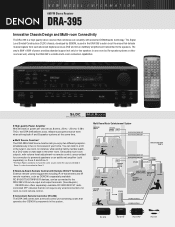
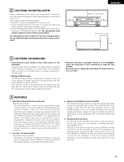
...s Video Select Function Allows you listen to one source (example: Tuner), while recording another source (example: CD). DENON ELECTRONICS. NEW MODEL I N F O R M AT I O N DRA-395 s Signal Level Divided Construction Chassis Design The circuit handling low-level signals has been divided into separate blocks to ensure ...an alternate audio input source, ideal for making unattended tape copies. The DRA-395 also has a 4-pole varactor diode in Japan BOX 867, PINE BROOK, NJ 07058-9777, USA TEL: 973-396-0810 www.denon.com DENON CANADA INC. 17 DENISON STREET, MARKHAM ONTARIO, CANADA L3R 1B5 TEL...
...s Video Select Function Allows you listen to one source (example: Tuner), while recording another source (example: CD). DENON ELECTRONICS. NEW MODEL I N F O R M AT I O N DRA-395 s Signal Level Divided Construction Chassis Design The circuit handling low-level signals has been divided into separate blocks to ensure ...an alternate audio input source, ideal for making unattended tape copies. The DRA-395 also has a 4-pole varactor diode in Japan BOX 867, PINE BROOK, NJ 07058-9777, USA TEL: 973-396-0810 www.denon.com DENON CANADA INC. 17 DENISON STREET, MARKHAM ONTARIO, CANADA L3R 1B5 TEL...
Owners Manual
Page 1
... mode d'emploi pour s'y référer ultérieurement en cas de question ou de problème. AM-FM STEREO RECEIVER DRA-395 OPERATING INSTRUCTIONS MODE D'EMPLOI B PRECISION AUDIO COMPONENT / STEREO RECEIVER DRA-395 CD PHONO TUNER CDR / TAPE VCR DVD / VDP V.AUX REMOTE SENSOR ON / STANDBY Multi Room Music Entertainment System ZONE 2 ZONE 3 SHIFT...
... mode d'emploi pour s'y référer ultérieurement en cas de question ou de problème. AM-FM STEREO RECEIVER DRA-395 OPERATING INSTRUCTIONS MODE D'EMPLOI B PRECISION AUDIO COMPONENT / STEREO RECEIVER DRA-395 CD PHONO TUNER CDR / TAPE VCR DVD / VDP V.AUX REMOTE SENSOR ON / STANDBY Multi Room Music Entertainment System ZONE 2 ZONE 3 SHIFT...
Owners Manual
Page 3
... appliance and cart combination to rain; or E. The user should be walked on a bed, sofa, rug, or similar surface that described in wire to the receiver, be cleaned only as to grounding electrodes, and requirements for example, near a swimming pool, and the like. 6. NATIONAL ELECTRICAL CODE ANTENNA LEAD IN WIRE ANTENNA...
... appliance and cart combination to rain; or E. The user should be walked on a bed, sofa, rug, or similar surface that described in wire to the receiver, be cleaned only as to grounding electrodes, and requirements for example, near a swimming pool, and the like. 6. NATIONAL ELECTRICAL CODE ANTENNA LEAD IN WIRE ANTENNA...
Owners Manual
Page 4
... the power operation switch to provide outstanding high fidelity reproduction of this product is provided with the connection cords. Always set for choosing the DENON AM-FM Stereo receiver. Listening to the Radio 21~23 ⁄0 Initialization of the Microprocessor 24 ⁄1 Last function memory 24 ⁄2 Troubleshooting 25 ⁄3 Specifications 26...
... the power operation switch to provide outstanding high fidelity reproduction of this product is provided with the connection cords. Always set for choosing the DENON AM-FM Stereo receiver. Listening to the Radio 21~23 ⁄0 Initialization of the Microprocessor 24 ⁄1 Last function memory 24 ⁄2 Troubleshooting 25 ⁄3 Specifications 26...
Owners Manual
Page 5
... or 3) allows the sub room output to the input jacks. Remote Control Functions The Remote Control (RC-894) commands not only the receiver but can each other are greatly reduced for viewing or listening Different sources can be reproduced with this unit's power cord and input/output ..., Versatile Amplifier High-Quality Power Amplifier: High-speed, high-power transistors employed in a subroom. 2. External remote control equipment, such as DENON's RC-616 and RC-617, can thus be generated if this happens, either turn down the VOLUME control or connect components to operate the...
... or 3) allows the sub room output to the input jacks. Remote Control Functions The Remote Control (RC-894) commands not only the receiver but can each other are greatly reduced for viewing or listening Different sources can be reproduced with this unit's power cord and input/output ..., Versatile Amplifier High-Quality Power Amplifier: High-speed, high-power transistors employed in a subroom. 2. External remote control equipment, such as DENON's RC-616 and RC-617, can thus be generated if this happens, either turn down the VOLUME control or connect components to operate the...
Owners Manual
Page 6
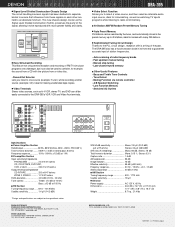
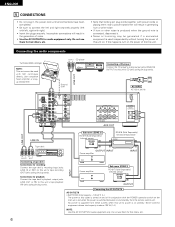
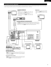
OUTPUT CD player RL RL DIGITAL AUDIO LINE OUT Ground wire RL LOOP ANT. LINE OUT INPUT LINE IN Sub room (ZONE 2) RC-617 (Sold Separately) Infrared sensor + RC-616 (Sold Separately) Infrared retransmitter + Tape deck R LR L R LR L OUTPUT INPUT Connecting a tape deck Connections for recording: Connect the tape deck's recording input jacks (LINE IN or REC) to this unit's tape playback (IN) jacks using pin plug cords. Never connect equipment whose total capacity is at standby. Connecting the audio components Turntable (MM cartridge) NOTE: This unit cannot be ...
OUTPUT CD player RL RL DIGITAL AUDIO LINE OUT Ground wire RL LOOP ANT. LINE OUT INPUT LINE IN Sub room (ZONE 2) RC-617 (Sold Separately) Infrared sensor + RC-616 (Sold Separately) Infrared retransmitter + Tape deck R LR L R LR L OUTPUT INPUT Connecting a tape deck Connections for recording: Connect the tape deck's recording input jacks (LINE IN or REC) to this unit's tape playback (IN) jacks using pin plug cords. Never connect equipment whose total capacity is at standby. Connecting the audio components Turntable (MM cartridge) NOTE: This unit cannot be ...
Owners Manual
Page 7
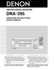
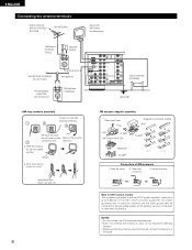
Using an improper cable can result in a drop in sound quality. • When making connections, also refer to the VIDEO (yellow) VCR OUT jack using pin plug cords. AM R ANTENNA TERMINALS PRE OUT SUB WOOFER FM RCOAX. 75 L R L R ZONE 2 R L L ZONE OUT 3 MULTI ROOM R PHONO IN L CD SIGNAL GND DVD/ VDP V. AUDIO OUT AUDIO IN VIDEO IN VIDEO IN VIDEO OUT VIDEO IN Sub room (ZONE 3) Monitor TV R LR L Video deck R L R L OUT IN OUT IN AUDIO VIDEO Connecting a video decks Video input/output connections: • Connect the video deck's video output jack (VIDEO OUT) to the ...
Using an improper cable can result in a drop in sound quality. • When making connections, also refer to the VIDEO (yellow) VCR OUT jack using pin plug cords. AM R ANTENNA TERMINALS PRE OUT SUB WOOFER FM RCOAX. 75 L R L R ZONE 2 R L L ZONE OUT 3 MULTI ROOM R PHONO IN L CD SIGNAL GND DVD/ VDP V. AUDIO OUT AUDIO IN VIDEO IN VIDEO IN VIDEO OUT VIDEO IN Sub room (ZONE 3) Monitor TV R LR L Video deck R L R L OUT IN OUT IN AUDIO VIDEO Connecting a video decks Video input/output connections: • Connect the video deck's video output jack (VIDEO OUT) to the ...
Owners Manual
Page 8
With the antenna on wall, etc. 8 FM antenna adapter assembly Open the Cover PULL PULL CLAMP ANTENNA ADAPTER REMOVE CLAMP 75 Ω/ohms COAXIAL CABLE SHUT 14mm CLAMP 9mm 5mm 3C-2V 19mm 14mm 5mm 5C-2V Connection of the panel. direction. With the antenna attach to the point of the NEC which provides guidelines for proper grounding and, in the reverse 4 connection line. Return the lever. Note to Article 820-40 of cable entry as practical. NOTES: • Do not connect two FM antennas simultaneously. • Even if an external AM antenna is provided to call the ...
With the antenna on wall, etc. 8 FM antenna adapter assembly Open the Cover PULL PULL CLAMP ANTENNA ADAPTER REMOVE CLAMP 75 Ω/ohms COAXIAL CABLE SHUT 14mm CLAMP 9mm 5mm 3C-2V 19mm 14mm 5mm 5C-2V Connection of the panel. direction. With the antenna attach to the point of the NEC which provides guidelines for proper grounding and, in the reverse 4 connection line. Return the lever. Note to Article 820-40 of cable entry as practical. NOTES: • Do not connect two FM antennas simultaneously. • Even if an external AM antenna is provided to call the ...
Owners Manual
Page 9
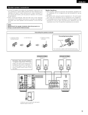
NOTE: NEVER touch the speaker terminals when the power is on the screen may be disturbed by the speaker's magnetism. If this effect. Mismatching of polarities will result in weak central sound, unclear orientation of the various instruments, and the sense of direction of the stereo being impaired. • When making sure that none of the individual conductors of the speaker cord come in contact with adjacent terminals, with other speaker cord conductors, or with the rear panel. Connecting banana plugs banana plug Turn clockwise to tighten, then insert the banana plug. •...
NOTE: NEVER touch the speaker terminals when the power is on the screen may be disturbed by the speaker's magnetism. If this effect. Mismatching of polarities will result in weak central sound, unclear orientation of the various instruments, and the sense of direction of the stereo being impaired. • When making sure that none of the individual conductors of the speaker cord come in contact with adjacent terminals, with other speaker cord conductors, or with the rear panel. Connecting banana plugs banana plug Turn clockwise to tighten, then insert the banana plug. •...
Owners Manual
Page 10
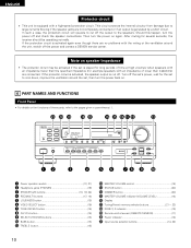
... off the set's power, wait for several seconds, the receiver should be activated if the set to cool down, improve the ventilation around the unit, switch off the power and contact a DENON service center. This circuit protects the internal circuitry from damage ...due to large currents flowing if the speaker jacks are no problems with an impedance of these parts, refer to the pages given in parentheses ( ). @1 @0 !9 !8 !7 !6 !5 !4 !38 !2 !1 B PRECISION AUDIO COMPONENT / STEREO RECEIVER DRA-395 CD...
... off the set's power, wait for several seconds, the receiver should be activated if the set to cool down, improve the ventilation around the unit, switch off the power and contact a DENON service center. This circuit protects the internal circuitry from damage ...due to large currents flowing if the speaker jacks are no problems with an impedance of these parts, refer to the pages given in parentheses ( ). @1 @0 !9 !8 !7 !6 !5 !4 !38 !2 !1 B PRECISION AUDIO COMPONENT / STEREO RECEIVER DRA-395 CD...
Owners Manual
Page 11
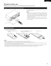
e Close the lid. Replace it come in malfunction, so keep the set . (The included battery is exposed to direct sunlight or other strong light, or if operated from an angle. • Neon signs or other devices emitting pulse-type noise nearby may result in contact with a new battery as soon as possible.) • When replacing the batteries, after removing them wait for an extended period of time. • If batteries leak, dispose of them immediately. Inserting the batteries For remote control unit (RC-894) q Press as possible. Avoid touching the leaked material or letting it ...
e Close the lid. Replace it come in malfunction, so keep the set . (The included battery is exposed to direct sunlight or other strong light, or if operated from an angle. • Neon signs or other devices emitting pulse-type noise nearby may result in contact with a new battery as soon as possible.) • When replacing the batteries, after removing them wait for an extended period of time. • If batteries leak, dispose of them immediately. Inserting the batteries For remote control unit (RC-894) q Press as possible. Avoid touching the leaked material or letting it ...
Owners Manual
Page 12
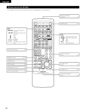
AUX DIMMER CH VOL SHIFT STATUS • VIDEO SELECT ª • • PRESET MASTER VOL ª MUTING ª B REMOTE CONTROL UNIT RC-894 Remote control signal transmitter 11) POWER buttons 13) TAPE 0, 1 : Play (reverse and forward) 6, 7 : Rewind and Fast-forward 2 : Stop 3 : Pause 4 REC : REC A / B : Tape A/B selection Input source selector buttons 14) VOLUME control buttons 14) MUTING button 19) Preset memory selector buttons 23) 12 AUX VCR DVD / VDP CD • PHONO DVD / VDP PRESET CDR / TAPE ª CD VCR A SPEAKER B TUNER CDR / TAPE V. CD 8, 9 : Auto ...
AUX DIMMER CH VOL SHIFT STATUS • VIDEO SELECT ª • • PRESET MASTER VOL ª MUTING ª B REMOTE CONTROL UNIT RC-894 Remote control signal transmitter 11) POWER buttons 13) TAPE 0, 1 : Play (reverse and forward) 6, 7 : Rewind and Fast-forward 2 : Stop 3 : Pause 4 REC : REC A / B : Tape A/B selection Input source selector buttons 14) VOLUME control buttons 14) MUTING button 19) Preset memory selector buttons 23) 12 AUX VCR DVD / VDP CD • PHONO DVD / VDP PRESET CDR / TAPE ª CD VCR A SPEAKER B TUNER CDR / TAPE V. CD 8, 9 : Auto ...
Owners Manual
Page 13
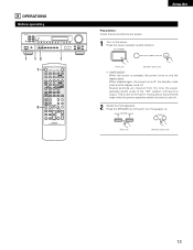
8 OPERATIONS Before operating B 1 12 1 1 2 OFF POWER ON RANDOM 6 7 8 9 REPEAT DISC SKIP 3 2 CD 1 ON MAIN OFF A / B 6 4 REC 7 3 2 0 TAPE 1 ZONE 2 ON • VOLUME OFF ª ZONE 3 MULTI ROOM ON • VOLUME OFF ª TUNER PHONO V. Press the power operation switch (button). ON / STANDBY OFF POWER ON (Main unit) (Remote control unit) • ON/STANDBY When the button is turned on the power. SPEAKER A B A SPEAKER B (Main unit) (Remote control unit) 13 AUX DIMMER CH VOL SHIFT STATUS • VIDEO SELECT ª • • PRESET ...
8 OPERATIONS Before operating B 1 12 1 1 2 OFF POWER ON RANDOM 6 7 8 9 REPEAT DISC SKIP 3 2 CD 1 ON MAIN OFF A / B 6 4 REC 7 3 2 0 TAPE 1 ZONE 2 ON • VOLUME OFF ª ZONE 3 MULTI ROOM ON • VOLUME OFF ª TUNER PHONO V. Press the power operation switch (button). ON / STANDBY OFF POWER ON (Main unit) (Remote control unit) • ON/STANDBY When the button is turned on the power. SPEAKER A B A SPEAKER B (Main unit) (Remote control unit) 13 AUX DIMMER CH VOL SHIFT STATUS • VIDEO SELECT ª • • PRESET ...
Owners Manual
Page 14
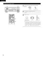
EX: CD CD CD (Main unit) (Remote control unit) 2 Start playback on page 15, if the volume for the program source to the various components' manuals. 3 Adjust the volume. ENGLISH Playing the program source 1 3 B MAIN OFF 6 7 0 TAPE 1 ZONE 2 ON • VOLUME OFF ª ZONE 3 MULTI ROOM ON • VOLUME OFF ª TUNER PHONO V. AUX VCR DVD / VDP CD • PHONO DVD / VDP PRESET CDR / TAPE ª CD VCR A SPEAKER B TUNER CDR / TAPE V. MASTER VOLUME • MASTER VOL The volume level is displayed on the master volume level display. (Main unit) ª...
EX: CD CD CD (Main unit) (Remote control unit) 2 Start playback on page 15, if the volume for the program source to the various components' manuals. 3 Adjust the volume. ENGLISH Playing the program source 1 3 B MAIN OFF 6 7 0 TAPE 1 ZONE 2 ON • VOLUME OFF ª ZONE 3 MULTI ROOM ON • VOLUME OFF ª TUNER PHONO V. AUX VCR DVD / VDP CD • PHONO DVD / VDP PRESET CDR / TAPE ª CD VCR A SPEAKER B TUNER CDR / TAPE V. MASTER VOLUME • MASTER VOL The volume level is displayed on the master volume level display. (Main unit) ª...
Owners Manual
Page 15
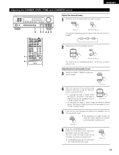
AUX VCR DVD / VDP CD • PHONO DVD / VDP PRESET CDR / TAPE ª CD VCR A SPEAKER B TUNER CDR / TAPE V. L R SW 2 Adjust the level of 2 dB.) 5 If you do not pass through the bass and treble adjustment circuits, providing higher quality sound. (Main unit) 6 Press the LOUDNESS button. TREBLE BASS (Main unit) 4 With the name of 1 dB. Adjusting the sound quality (tone) 3 Select the BASS or TREBLE whose level you want to produce a natural sound. TONE DEFEAT The signals do not want to music at a low volume. LOUDNESS (Main unit) 15 ENGLISH Adjusting the CHANNEL ...
AUX VCR DVD / VDP CD • PHONO DVD / VDP PRESET CDR / TAPE ª CD VCR A SPEAKER B TUNER CDR / TAPE V. L R SW 2 Adjust the level of 2 dB.) 5 If you do not pass through the bass and treble adjustment circuits, providing higher quality sound. (Main unit) 6 Press the LOUDNESS button. TREBLE BASS (Main unit) 4 With the name of 1 dB. Adjusting the sound quality (tone) 3 Select the BASS or TREBLE whose level you want to produce a natural sound. TONE DEFEAT The signals do not want to music at a low volume. LOUDNESS (Main unit) 15 ENGLISH Adjusting the CHANNEL ...
Owners Manual
Page 16
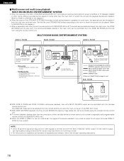
... RC-894 • Sold Separately • IR RETRANSMITTER RC-616 • IR SENSOR RC-617 • PROGRAMABLE REMOTE CONTROL UNIT RC-770 RC-616 B DRA-395 SPEAKER SYSTEM -B SYSTEM REMOTE CONTROL UNIT RC-894 RC-617 TV AMPLIFIRE RC-894 (or PROGRAMABLE REMOTE CONTROL UNIT RC-8000) ROOM-TO-ROOM REMOTE... CONTROL SYSTEM (separately sold programmable remote control unit (DENON RC-8000, etc.). SUB ROOM RC-617 RC-894 (or PROGRAMABLE REMOTE CONTROL UNIT RC-8000) With ZONE 2 ROOM and ZONE 3 ROOM multi-source...
... RC-894 • Sold Separately • IR RETRANSMITTER RC-616 • IR SENSOR RC-617 • PROGRAMABLE REMOTE CONTROL UNIT RC-770 RC-616 B DRA-395 SPEAKER SYSTEM -B SYSTEM REMOTE CONTROL UNIT RC-894 RC-617 TV AMPLIFIRE RC-894 (or PROGRAMABLE REMOTE CONTROL UNIT RC-8000) ROOM-TO-ROOM REMOTE... CONTROL SYSTEM (separately sold programmable remote control unit (DENON RC-8000, etc.). SUB ROOM RC-617 RC-894 (or PROGRAMABLE REMOTE CONTROL UNIT RC-8000) With ZONE 2 ROOM and ZONE 3 ROOM multi-source...
Owners Manual
Page 17
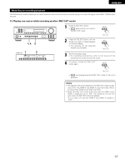
SELECT (Main unit) 3 Set the recording mode. • For operating instructions, refer to the manual of the component on the set and both the ZONE 2 and ZONE 3 modes are ON.) • When the REC OUT mode is pressed. To turn off , set the ZONE 2 and ZONE 3 modes to "OFF". 17 ENGLISH Multi-Source recording/playback The Multi-Source function allows you to record a source other than the source currently playing or to output its signal to the MULTI ZONE output terminal. [1] Playing one source while recording another (REC OUT mode) B 1 Press the REC OUT button. • REC ...
SELECT (Main unit) 3 Set the recording mode. • For operating instructions, refer to the manual of the component on the set and both the ZONE 2 and ZONE 3 modes are ON.) • When the REC OUT mode is pressed. To turn off , set the ZONE 2 and ZONE 3 modes to "OFF". 17 ENGLISH Multi-Source recording/playback The Multi-Source function allows you to record a source other than the source currently playing or to output its signal to the MULTI ZONE output terminal. [1] Playing one source while recording another (REC OUT mode) B 1 Press the REC OUT button. • REC ...
Owners Manual
Page 18
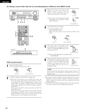
ENGLISH [2] Playing a source other than the one currently playing in the MULTI mode.) • PRESET ª (Remote control unit) NOTE: Note that this also switches the preset reception channel on the remote control unit. Press the SELECT button repeatedly until the desired source appears on /off . When using the ZONE 2 VOLUME • and ª buttons on the main unit when playing or recording the tuner in the MULTI mode. 2 The MULTI indicator and the ZONE 2 indicator light. ZONE 2 ZONE 2 OFF (Main unit) (Remote control unit) 5 The output level of the various zones can be...
ENGLISH [2] Playing a source other than the one currently playing in the MULTI mode.) • PRESET ª (Remote control unit) NOTE: Note that this also switches the preset reception channel on the remote control unit. Press the SELECT button repeatedly until the desired source appears on /off . When using the ZONE 2 VOLUME • and ª buttons on the main unit when playing or recording the tuner in the MULTI mode. 2 The MULTI indicator and the ZONE 2 indicator light. ZONE 2 ZONE 2 OFF (Main unit) (Remote control unit) 5 The output level of the various zones can be...
Owners Manual
Page 19
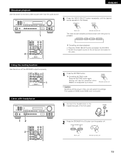
SPEAKER A SPEAKER B A B (Main unit) (Remote control unit) 19 AUX SOURCE Cancelling simulcast playback. • Press the VIDEO SELECT button and select the SOURCE. • Switch the program source to the component connected to the video. Cancelling MUTING mode. The outputs of ZONE 2 and ZONE 3 are not muted. 1 Connect the headphones to the headphones jack of the unit will also be cancelled when Master vol is pressed: DVD/VDP VCR V. VIDEO SELECT VIDEO SELECT 1 2 CD • PHONO DVD / VDP PRESET CDR / TAPE ª CD VCR A SPEAKER B TUNER CDR / TAPE V. Using ...
SPEAKER A SPEAKER B A B (Main unit) (Remote control unit) 19 AUX SOURCE Cancelling simulcast playback. • Press the VIDEO SELECT button and select the SOURCE. • Switch the program source to the component connected to the video. Cancelling MUTING mode. The outputs of ZONE 2 and ZONE 3 are not muted. 1 Connect the headphones to the headphones jack of the unit will also be cancelled when Master vol is pressed: DVD/VDP VCR V. VIDEO SELECT VIDEO SELECT 1 2 CD • PHONO DVD / VDP PRESET CDR / TAPE ª CD VCR A SPEAKER B TUNER CDR / TAPE V. Using ...