
Owners Manual - English
Page 4
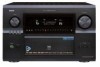
...mode 56, 57 DTS NEO:6 mode 58 Cable indications 27 The video conversion function 28 On screen display for choosing the DENON AVR-5805CI AV Surround Receiver. This remarkable component has been engineered to provide superb surround sound listening with DVI-D terminals 37 Connecting IEEE1394 devices 38 Connecting... unit 9 Switching between HDMI and DVI-D monitor output 45 Part names and functions Selection of resolution setting (SCALE 45 Front panel 10, 11 Combining the currently playing sound with the desired Display 12 image (VIDEO SELECT 45 Remote control unit 13 Video ...
...mode 56, 57 DTS NEO:6 mode 58 Cable indications 27 The video conversion function 28 On screen display for choosing the DENON AVR-5805CI AV Surround Receiver. This remarkable component has been engineered to provide superb surround sound listening with DVI-D terminals 37 Connecting IEEE1394 devices 38 Connecting... unit 9 Switching between HDMI and DVI-D monitor output 45 Part names and functions Selection of resolution setting (SCALE 45 Front panel 10, 11 Combining the currently playing sound with the desired Display 12 image (VIDEO SELECT 45 Remote control unit 13 Video ...

Owners Manual - English
Page 10
Getting Started Part names and functions Front panel • For details on the functions of these parts, refer to the pages given in parentheses ( ). !3 !2 !1 !0 o !8 !4 !5 !6 !7 !9 @0 qw e r @1 @2 @3 @4 @5 ty ui @6 @7 @8 @9 #0 #1 #3 #5 #7 #9 $1 $2 $3 $5 $7 $9 %1 #2 #4 #6 #8 $0 $4 $6 $8 %0 10
Getting Started Part names and functions Front panel • For details on the functions of these parts, refer to the pages given in parentheses ( ). !3 !2 !1 !0 o !8 !4 !5 !6 !7 !9 @0 qw e r @1 @2 @3 @4 @5 ty ui @6 @7 @8 @9 #0 #1 #3 #5 #7 #9 $1 $2 $3 $5 $7 $9 %1 #2 #4 #6 #8 $0 $4 $6 $8 %0 10

Owners Manual - English
Page 16
...Turn off . The fan is cut off the set's power, wait for the set to switch off the power and contact a DENON service center. Insert the cable. 3. When the protection circuit is activated, the speaker output is activated under circumstances such as when ...panel and screws. 2 Speaker Impedance • Speakers with a high-speed protection circuit. Either tightly twist or terminate the core wires. 2. NOTE: • NEVER touch the speaker terminals when the power is equipped with an impedance of from rising. Protector circuit This unit is on. Cooling fan The AVR-5805CI...
...Turn off . The fan is cut off the set's power, wait for the set to switch off the power and contact a DENON service center. Insert the cable. 3. When the protection circuit is activated, the speaker output is activated under circumstances such as when ...panel and screws. 2 Speaker Impedance • Speakers with a high-speed protection circuit. Either tightly twist or terminate the core wires. 2. NOTE: • NEVER touch the speaker terminals when the power is equipped with an impedance of from rising. Protector circuit This unit is on. Cooling fan The AVR-5805CI...

Owners Manual - English
Page 21
... measurements. Please do not stand between the speakers and microphone. The optional standard microphone is not possible to the SETUP MIC jack on the front panel of the listener. SYSTEM SETUP ENTER ON CURSOR When placing the microphone, adjust the height so that there are no obstacles. It is... DENON DM-S305 sold separately. NOTE: • Do not disconnect the microphone until the settings are any obstacles between or near the speakers and the microphone ...
... measurements. Please do not stand between the speakers and microphone. The optional standard microphone is not possible to the SETUP MIC jack on the front panel of the listener. SYSTEM SETUP ENTER ON CURSOR When placing the microphone, adjust the height so that there are no obstacles. It is... DENON DM-S305 sold separately. NOTE: • Do not disconnect the microphone until the settings are any obstacles between or near the speakers and the microphone ...

Owners Manual - English
Page 32
... playback source equipment be the same type that is necessary that the type of the component connected to the OPTICAL 3 (to 5) OUT terminal on the AVR-5805CI's rear panel to any terminal other than the OPTICAL 3 (to the digital audio connections. • To connect the digital audio output from either the coaxial or... video outputs are also provided. If you can choose from the DVD recorder, you choose to use the coaxial connection, it is connected to the AVR-5805CI VCR-1 (to your DVD recorder.
... playback source equipment be the same type that is necessary that the type of the component connected to the OPTICAL 3 (to 5) OUT terminal on the AVR-5805CI's rear panel to any terminal other than the OPTICAL 3 (to the digital audio connections. • To connect the digital audio output from either the coaxial or... video outputs are also provided. If you can choose from the DVD recorder, you choose to use the coaxial connection, it is connected to the AVR-5805CI VCR-1 (to your DVD recorder.

Owners Manual - English
Page 34
... L L L R R R A AUDIO IN L L L R R R D OPTICAL OUT D OPTICAL IN NOTE: • Do not connect the output of the component connected to the OPTICAL 5 OUT terminal on the AVR-5805CI's rear panel to any terminal other noise is generated when the ground wire is connected to perform analog dubbing from moving magnet (MM) and high output moving...
... L L L R R R A AUDIO IN L L L R R R D OPTICAL OUT D OPTICAL IN NOTE: • Do not connect the output of the component connected to the OPTICAL 5 OUT terminal on the AVR-5805CI's rear panel to any terminal other noise is generated when the ground wire is connected to perform analog dubbing from moving magnet (MM) and high output moving...

Owners Manual - English
Page 39
... FM antennas simultaneously. • Even if an external AM antenna is provided to call the CATV system installer's attention to Article 820-40 of the panel. 39 Mount b. Bend in particular, specifies that the cable ground shall be connected directly. Insert the conductor. 3. With the antenna on wall, etc. Installation hole...
... FM antennas simultaneously. • Even if an external AM antenna is provided to call the CATV system installer's attention to Article 820-40 of the panel. 39 Mount b. Bend in particular, specifies that the cable ground shall be connected directly. Insert the conductor. 3. With the antenna on wall, etc. Installation hole...

Owners Manual - English
Page 40
...Radio" ( page 71). All rights reserved. • XM Ready is the XM Ready® receiver. Press the ON/STANDBY button on the rear panel. • Position the Home Dock antenna near a south-facing window to the operating mode. ... before using an external controller connected to turn off the power from the external control. 3. You can receive XM® Satellite Radio by connecting to the XM Mini-Tuner and Home Dock (includes home antenna,...: 1. MX Connecting Other Sources Connecting the XM terminal • AVR-5805CI is a registered trademark of the XM Mini-Tuner and Home Dock.
...Radio" ( page 71). All rights reserved. • XM Ready is the XM Ready® receiver. Press the ON/STANDBY button on the rear panel. • Position the Home Dock antenna near a south-facing window to the operating mode. ... before using an external controller connected to turn off the power from the external control. 3. You can receive XM® Satellite Radio by connecting to the XM Mini-Tuner and Home Dock (includes home antenna,...: 1. MX Connecting Other Sources Connecting the XM terminal • AVR-5805CI is a registered trademark of the XM Mini-Tuner and Home Dock.

Owners Manual - English
Page 45
...Speaker Configuration" ( page 140, 141). Cancel the VIDEO SELECT mode if you want to display the control panel. NOTE: • To prevent hearing loss, be selected for the HDMI video output. • If the...B is stored in the XM or Network Audio, the picture switches to the picture selected from the control panel display. SURROUND A SURROUND B SURROUND A+B This operation is pressed. For description of the each time the SPEAKER...no video signals of a DVD, etc., are connected to the AVR-5805CI and the DVD, etc., are connected. Press the MUTE button. Video on the display.
...Speaker Configuration" ( page 140, 141). Cancel the VIDEO SELECT mode if you want to display the control panel. NOTE: • To prevent hearing loss, be selected for the HDMI video output. • If the...B is stored in the XM or Network Audio, the picture switches to the picture selected from the control panel display. SURROUND A SURROUND B SURROUND A+B This operation is pressed. For description of the each time the SPEAKER...no video signals of a DVD, etc., are connected to the AVR-5805CI and the DVD, etc., are connected. Press the MUTE button. Video on the display.

Owners Manual - English
Page 46
Each time an operation is output in sequence. 2 Front panel display Press the STATUS button. Input mode • The AVR-5805CI has an AUTO signal detection mode that can be generated when using this mode, the types of the display. If no digital signal is also ....IN -2 EXT.IN -1 DTS ANALOG AUTO (All auto mode): In this mode to AVR5805CI's VIDEO MONITOR OUT terminal. Note that operation appears on the front panel display. IN STATUS INPUT MODE DIMMER CURSOR CURSOR SURROUND PARAMETER ON SCREEN Checking the currently playing program source, etc. 2 On screen display Press the ON...
Each time an operation is output in sequence. 2 Front panel display Press the STATUS button. Input mode • The AVR-5805CI has an AUTO signal detection mode that can be generated when using this mode, the types of the display. If no digital signal is also ....IN -2 EXT.IN -1 DTS ANALOG AUTO (All auto mode): In this mode to AVR5805CI's VIDEO MONITOR OUT terminal. Note that operation appears on the front panel display. IN STATUS INPUT MODE DIMMER CURSOR CURSOR SURROUND PARAMETER ON SCREEN Checking the currently playing program source, etc. 2 On screen display Press the ON...

Owners Manual - English
Page 55
The display is preset, you may see a brief message in the front panel display, to keep the programs at lower volumes, the night mode improves listenability. Display Dial.Norm Offset -4dB Night mode When listening at night or ... calibrated theatrical levels, you can not be selected. Basic Operation 55 For example, if you see the following message: "Dial Norm + 4 dB" in the front panel display which has been encoded in Dolby Digital, sometimes you may wish to "ON", the "D.COMP" surround parameter can choose your preferred volume setting for...
The display is preset, you may see a brief message in the front panel display, to keep the programs at lower volumes, the night mode improves listenability. Display Dial.Norm Offset -4dB Night mode When listening at night or ... calibrated theatrical levels, you can not be selected. Basic Operation 55 For example, if you see the following message: "Dial Norm + 4 dB" in the front panel display which has been encoded in Dolby Digital, sometimes you may wish to "ON", the "D.COMP" surround parameter can choose your preferred volume setting for...

Owners Manual - English
Page 62
... CONTROL BACK ENTER SURROUND PARAMETER CURSOR 2 Surround parameters y EFFECT: This parameter turns the effect signals with multi surround mode speaker effects on the main unit's panel. The level can be set within the range of 0 to 300 ms. Tone control setting • Use the tone control setting to a low level if...
... CONTROL BACK ENTER SURROUND PARAMETER CURSOR 2 Surround parameters y EFFECT: This parameter turns the effect signals with multi surround mode speaker effects on the main unit's panel. The level can be set within the range of 0 to 300 ms. Tone control setting • Use the tone control setting to a low level if...

Owners Manual - English
Page 67
Recalling preset stations 2 Recalling preset stations from the main unit's panel 1 Press the TUNING PRESET button. 2 Turn the FUNCTION knob and select the desired preset channel. 2 Traffic Program (TP) • TP identifies programs that carry traffic ... text messages that appear on the display. 67 Checking the preset stations RDS (Radio Data System) Basic Operation • The preset (broadcast) stations can be received on this unit: NOTE: • The operations described below pressing the RDS SEARCH button will not function in areas in your area before you to...
Recalling preset stations 2 Recalling preset stations from the main unit's panel 1 Press the TUNING PRESET button. 2 Turn the FUNCTION knob and select the desired preset channel. 2 Traffic Program (TP) • TP identifies programs that carry traffic ... text messages that appear on the display. 67 Checking the preset stations RDS (Radio Data System) Basic Operation • The preset (broadcast) stations can be received on this unit: NOTE: • The operations described below pressing the RDS SEARCH button will not function in areas in your area before you to...

Owners Manual - English
Page 75
... your provider is of 32, 44.1 or 48 kHz. • The AVR-5805CI is compatible with WMA meta tags. • With the AVR-5805CI, the folder names, file names, etc., can be displayed on the AVR-5805CI's rear panel, the other side to the ETHERNET terminal on the main unit's display and... the OSD. It is not compatible with "MPEG-2 Audio Layer-3", "MPEG-2.5 Audio Layer-3", "MP1" or "MP2" files. • The AVR-5805CI is compatible with sampling frequencies of the...
... your provider is of 32, 44.1 or 48 kHz. • The AVR-5805CI is compatible with WMA meta tags. • With the AVR-5805CI, the folder names, file names, etc., can be displayed on the AVR-5805CI's rear panel, the other side to the ETHERNET terminal on the main unit's display and... the OSD. It is not compatible with "MPEG-2 Audio Layer-3", "MPEG-2.5 Audio Layer-3", "MP1" or "MP2" files. • The AVR-5805CI is compatible with sampling frequencies of the...

Owners Manual - English
Page 80
...place "ESCIENT" before the server name. Volume control screen NOTE: • To use this IP address in Internet Explorer to display the AVR-5805CI's control panel. • Operate in your favorites • The same operations as with normal Internet browsing to "System Setup". Function selection screen NOTE:... below are the same as for Internet radio stations can be used on the computer connected to the AVR-5805CI over the network to operate the AVR5805CI. • Check the AVR-5805CI's IP address ( page 138) beforehand and input this function, set "Standby Mode Power Saving" at...
...place "ESCIENT" before the server name. Volume control screen NOTE: • To use this IP address in Internet Explorer to display the AVR-5805CI's control panel. • Operate in your favorites • The same operations as with normal Internet browsing to "System Setup". Function selection screen NOTE:... below are the same as for Internet radio stations can be used on the computer connected to the AVR-5805CI over the network to operate the AVR5805CI. • Check the AVR-5805CI's IP address ( page 138) beforehand and input this function, set "Standby Mode Power Saving" at...
Owners Manual - English
Page 102
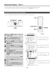
Part 1 • You can change setting using the buttons on the front panel or remote control unit. For the contents of a system menu and the initial setting of system setup so that it may be fitting for your ...
Part 1 • You can change setting using the buttons on the front panel or remote control unit. For the contents of a system menu and the initial setting of system setup so that it may be fitting for your ...

Owners Manual - English
Page 103
... screen display when you use the on screen display examples are changed with an alpha-numeric front panel display tube that you make system adjustments. No. Part 1 On screen display and front display • The AVR-5805CI is equipped with an intuitive and easy-to-understand on screen display, and is equipped with...
... screen display when you use the on screen display examples are changed with an alpha-numeric front panel display tube that you make system adjustments. No. Part 1 On screen display and front display • The AVR-5805CI is equipped with an intuitive and easy-to-understand on screen display, and is equipped with...

Owners Manual - English
Page 104
... "System Setup Menu", then press the ENTER button. • The "Audio Input Setup" menu appears. • The OPTICAL 3, 4 and 5 terminals on the AVR-5805CI's rear panel to any terminal other than the OPTICAL 3 (to 5) IN terminal. 2 Press the CURSOR D or H button to select "Digital In Assign", then press the ... digital audio signals to "OFF". Select from the set terminal. 104 IN or IEEE1394). If the signal cannot be able to transferred by DENON LINK, the unit automatically changes over the input to 5. Advanced Setup - If the same digital input terminal is AUTO and the signals are...
... "System Setup Menu", then press the ENTER button. • The "Audio Input Setup" menu appears. • The OPTICAL 3, 4 and 5 terminals on the AVR-5805CI's rear panel to any terminal other than the OPTICAL 3 (to 5) IN terminal. 2 Press the CURSOR D or H button to select "Digital In Assign", then press the ... digital audio signals to "OFF". Select from the set terminal. 104 IN or IEEE1394). If the signal cannot be able to transferred by DENON LINK, the unit automatically changes over the input to 5. Advanced Setup - If the same digital input terminal is AUTO and the signals are...

Owners Manual - English
Page 129
... "R1" to "R5" are indicated on the speaker terminals on the setting at "Channel Setup". (c) The number of free power amplifiers depends on the AVR-5805CI's rear panel. • The channels for which the power amplifier can be assigned differ according to . Selecting the speaker outputs freely (b) Assign the power amplifier to the...
... "R1" to "R5" are indicated on the speaker terminals on the setting at "Channel Setup". (c) The number of free power amplifiers depends on the AVR-5805CI's rear panel. • The channels for which the power amplifier can be assigned differ according to . Selecting the speaker outputs freely (b) Assign the power amplifier to the...

Owners Manual - English
Page 135
... the trigger out terminal turns off . OFF: When that input source is selected, the power supplied from the trigger out terminal turns on the rear panel can be used to control other devices with compatible trigger inputs, such as motorized screens, motorized screen masking, motorized drapes, and other trigger-controlled devices...
... the trigger out terminal turns off . OFF: When that input source is selected, the power supplied from the trigger out terminal turns on the rear panel can be used to control other devices with compatible trigger inputs, such as motorized screens, motorized screen masking, motorized drapes, and other trigger-controlled devices...
