Literature/Product Sheet
Page 2
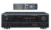
... (for speakers A): Large binding post speaker terminals has been provided for all of DENON's high-grade A/V receiver, the AVR-1603 lets you adjust delay times and other parameters so that program. ■ Multi-Function Preset Memory Remote Controller The supplied system remote controller features a large selection of DTS Technology. The most frequently used buttons are...
... (for speakers A): Large binding post speaker terminals has been provided for all of DENON's high-grade A/V receiver, the AVR-1603 lets you adjust delay times and other parameters so that program. ■ Multi-Function Preset Memory Remote Controller The supplied system remote controller features a large selection of DTS Technology. The most frequently used buttons are...
Owners Manual
Page 4
...the power operation switch to provide superb surround sound listening with the connection cords. AUX terminal The AVR-1604/684's front panel is provided with an immense array of features, we recommend that before you...outstanding high fidelity reproduction of your favorite music sources. After reading, store this instructions along with a V. AUX terminal. Using the Remote Control Unit 16 ⁄0 Setting up the Speaker Systems 8 , Connections 9~15 . Always set . • Before turning ... instructions may differ from the actual set for choosing the DENON A/V Surround receiver.
...the power operation switch to provide superb surround sound listening with the connection cords. AUX terminal The AVR-1604/684's front panel is provided with an immense array of features, we recommend that before you...outstanding high fidelity reproduction of your favorite music sources. After reading, store this instructions along with a V. AUX terminal. Using the Remote Control Unit 16 ⁄0 Setting up the Speaker Systems 8 , Connections 9~15 . Always set . • Before turning ... instructions may differ from the actual set for choosing the DENON A/V Surround receiver.
Owners Manual
Page 6
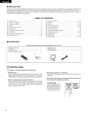
... 35) @2 Master volume indicator (VOLUME LEVEL 34) @3 Display @4 Preset station select buttons 51, 53) @5 BAND button 52) @6 SIGNAL indicators 34) @7 INPUT mode indicators 34) @8 Remote control sensor (REMOTE SENSOR 16) @9 Power operation indicator (ON/STANDBY) #0 INPUT SELECTOR knob 33) 6 ENGLISH 5 PART NAMES AND FUNCTIONS Front Panel • For details on the functions...
... 35) @2 Master volume indicator (VOLUME LEVEL 34) @3 Display @4 Preset station select buttons 51, 53) @5 BAND button 52) @6 SIGNAL indicators 34) @7 INPUT mode indicators 34) @8 Remote control sensor (REMOTE SENSOR 16) @9 Power operation indicator (ON/STANDBY) #0 INPUT SELECTOR knob 33) 6 ENGLISH 5 PART NAMES AND FUNCTIONS Front Panel • For details on the functions...
Owners Manual
Page 7
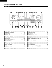
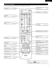
LED (indicator 28, 31) SURROUND buttons 34, 37, 47) ENGLISH Remote control signal transmitter 16) POWER buttons 18, 28~30, 32) Input source selector buttons 28~31, 33, 39) Tuner system/ System buttons 27, 30, 52, ..., 38, 40) SURROUND BACK/ RETURN button 29, 43) SPEAKER select button 32) DIMMER button 35) NOTE: • The shaded buttons do not function with the AVR-1604/684. (Nothing happens when they are pressed.) 7 Remote control unit • For details on the functions of these parts, refer to the pages given in parentheses ( ).
LED (indicator 28, 31) SURROUND buttons 34, 37, 47) ENGLISH Remote control signal transmitter 16) POWER buttons 18, 28~30, 32) Input source selector buttons 28~31, 33, 39) Tuner system/ System buttons 27, 30, 52, ..., 38, 40) SURROUND BACK/ RETURN button 29, 43) SPEAKER select button 32) DIMMER button 35) NOTE: • The shaded buttons do not function with the AVR-1604/684. (Nothing happens when they are pressed.) 7 Remote control unit • For details on the functions of these parts, refer to the pages given in parentheses ( ).
Owners Manual
Page 8
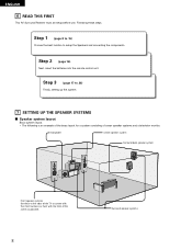
... example of the basic layout for a system consisting of the screen as possible. 8 Surround speaker systems Step 2 (page 16) Next, insert the batteries into the remote control unit. Step 3 (page 17 to setup the Speakers and connecting the components. Following these at the sides of the TV or screen with their... seven speaker systems and a television monitor: Subwoofer Center speaker system Surround back speaker system Front speaker systems Set these steps. ENGLISH 6 READ THIS FIRST This AV Surround Receiver must be setup before use.
... example of the basic layout for a system consisting of the screen as possible. 8 Surround speaker systems Step 2 (page 16) Next, insert the batteries into the remote control unit. Step 3 (page 17 to setup the Speakers and connecting the components. Following these at the sides of the TV or screen with their... seven speaker systems and a television monitor: Subwoofer Center speaker system Surround back speaker system Front speaker systems Set these steps. ENGLISH 6 READ THIS FIRST This AV Surround Receiver must be setup before use.
Owners Manual
Page 9
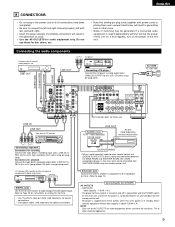
.... Incomplete connections will result in generating hum or other noise. • Noise or humming may be controlled from ANOTHER ROOM using the remote control unit. If this happens, turn on and standby from these outlets is used independently without turning the power of this unit on ...RL DIGITAL AUDIO Connecting a CD player Connect the CD player's analog output jacks (ANALOG OUTPUT) to -room remote control unit (DENON RC-616, 617 or 618) is supplied from the remote control unit. Extension jacks for future use them near a power transformer will result in the generation of the ...
.... Incomplete connections will result in generating hum or other noise. • Noise or humming may be controlled from ANOTHER ROOM using the remote control unit. If this happens, turn on and standby from these outlets is used independently without turning the power of this unit on ...RL DIGITAL AUDIO Connecting a CD player Connect the CD player's analog output jacks (ANALOG OUTPUT) to -room remote control unit (DENON RC-616, 617 or 618) is supplied from the remote control unit. Extension jacks for future use them near a power transformer will result in the generation of the ...
Owners Manual
Page 16
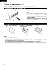
.... • Neon signs or other devices emitting pulse-type noise nearby may result in contact with clothing, etc. ENGLISH 9 USING THE REMOTE CONTROL UNIT Following the procedure outlined below, insert the batteries before installing new batteries. • Have replacement batteries on the diagram. Approx.... 23 feet/7 m 30° 30° NOTES: • The remote control unit can be replaced as quickly as possible.) 16 Inserting the batteries q Press as possible. Replace it come in malfunction, so keep...
.... • Neon signs or other devices emitting pulse-type noise nearby may result in contact with clothing, etc. ENGLISH 9 USING THE REMOTE CONTROL UNIT Following the procedure outlined below, insert the batteries before installing new batteries. • Have replacement batteries on the diagram. Approx.... 23 feet/7 m 30° 30° NOTES: • The remote control unit can be replaced as quickly as possible.) 16 Inserting the batteries q Press as possible. Replace it come in malfunction, so keep...
Owners Manual
Page 18
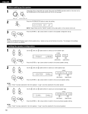
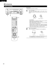
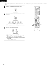
... 1 Check that point are correct, then press the POWER operation switch on the main unit or the POWER button on the remote control unit to turn on the power. (Main unit) (Remote control unit) 2 Press the SYSTEM SETUP button to enter the setting. *SYSTEM SET UP NOTE: Please make sure the ..."AUDIO" position of the slide switch on the remote control unit. 3 Press the ENTER or (down) button to switch to the speaker configuration...
... 1 Check that point are correct, then press the POWER operation switch on the main unit or the POWER button on the remote control unit to turn on the power. (Main unit) (Remote control unit) 2 Press the SYSTEM SETUP button to enter the setting. *SYSTEM SET UP NOTE: Please make sure the ..."AUDIO" position of the slide switch on the remote control unit. 3 Press the ENTER or (down) button to switch to the speaker configuration...
Owners Manual
Page 23
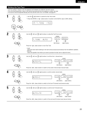
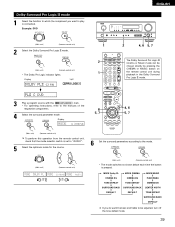
Setting the Test Tone • Use this setting to adjust to that the playback level between the different channel is equal. • From the listening position, listen to the test tones produced from the speakers to adjust the level. • The level can also be adjusted directly from the remote control unit. (For details, see page 37.) 1 • Use the (left) button to switch the Test Tone mode. • Press the ENTER or (down) button to switch to the DIGITAL input (COAX) setting. 15 T.TONE
Setting the Test Tone • Use this setting to adjust to that the playback level between the different channel is equal. • From the listening position, listen to the test tones produced from the speakers to adjust the level. • The level can also be adjusted directly from the remote control unit. (For details, see page 37.) 1 • Use the (left) button to switch the Test Tone mode. • Press the ENTER or (down) button to switch to the DIGITAL input (COAX) setting. 15 T.TONE
Owners Manual
Page 27
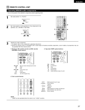
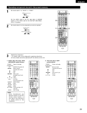
...Forward play 0 : Reverse play A/B : Switch between auto and mono MEMORY : Preset memory NOTE: • TUNER can be operated when the switch is compatible with this remote control is at "AUDIO" position. 27 Tape deck (TAPE) system buttons 6, 7 2 1 8, 9 3 DISC SKIP+ : Manual search (forward and reverse) : Stop...the position for CD changers only) 3. CD player (CD) and CD recorder and MD recorder (CDR/MD) system buttons 2. 11 REMOTE CONTROL UNIT Operating DENON audio components • Turn on the power of components may not be operated. (CD, CDR/MD or Tape deck) 1 3 ...
...Forward play 0 : Reverse play A/B : Switch between auto and mono MEMORY : Preset memory NOTE: • TUNER can be operated when the switch is compatible with this remote control is at "AUDIO" position. 27 Tape deck (TAPE) system buttons 6, 7 2 1 8, 9 3 DISC SKIP+ : Manual search (forward and reverse) : Stop...the position for CD changers only) 3. CD player (CD) and CD recorder and MD recorder (CDR/MD) system buttons 2. 11 REMOTE CONTROL UNIT Operating DENON audio components • Turn on the power of components may not be operated. (CD, CDR/MD or Tape deck) 1 3 ...
Owners Manual
Page 28
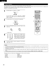
... 8 9 0 Referring to operate components of other makes of components can be set for one type of remote control code. The preset codes are emitted while setting the preset memory. ENGLISH Preset memory DENON and other manufacturers without using the learning function by setting the preset memory. Operation is not possible for...of Preset Codes, use more than one component only among the following: CDR/MD, DVD/VDP and DBS/CABLE. This remote control unit can be operated by registering the manufacturer of the component as follows upon shipment from the factory and after resetting...
... 8 9 0 Referring to operate components of other makes of components can be set for one type of remote control code. The preset codes are emitted while setting the preset memory. ENGLISH Preset memory DENON and other manufacturers without using the learning function by setting the preset memory. Operation is not possible for...of Preset Codes, use more than one component only among the following: CDR/MD, DVD/VDP and DBS/CABLE. This remote control unit can be operated by registering the manufacturer of the component as follows upon shipment from the factory and after resetting...
Owners Manual
Page 29
... mode switch 1 to the component's operating instructions. Digital video disc player (DVD, DVD SETUP) system buttons POWER : Power on/standby (ON/SOURCE) OFF : DENON DVD power off 6,7 : Manual search (forward and reverse) 2 : Stop 1 : Play 8,9 : Auto search (to beginning of track) 3 : Pause 0...setting NOTE: • Some manufacturers use different names for that component. 2. Video disc player (VDP) system buttons POWER : Power on remote control for the DVD remote control buttons, so also refer to the instructions on /standby (ON/SOURCE) 6,7 : Manual search (forward and reverse) 2 : ...
... mode switch 1 to the component's operating instructions. Digital video disc player (DVD, DVD SETUP) system buttons POWER : Power on/standby (ON/SOURCE) OFF : DENON DVD power off 6,7 : Manual search (forward and reverse) 2 : Stop 1 : Play 8,9 : Auto search (to beginning of track) 3 : Pause 0...setting NOTE: • Some manufacturers use different names for that component. 2. Video disc player (VDP) system buttons POWER : Power on remote control for the DVD remote control buttons, so also refer to the instructions on /standby (ON/SOURCE) 6,7 : Manual search (forward and reverse) 2 : ...
Owners Manual
Page 32
Several seconds are proper. 1 Turn on the power. Press the SPEAKER A or B button to turn on the power. (Main unit) (Remote control unit) • ON/STANDBY When the button is due to the built-in muting circuit that all connections are required from the time the ... switch is turned on and off . When pressed again, the power turns off, the standby mode is set to turn the speaker on. (Main unit) (Remote control unit) • The front speaker A, B setting can be also be changed with the SPEAKER button on and the display lights after approximately 1 second. Press...
Several seconds are proper. 1 Turn on the power. Press the SPEAKER A or B button to turn on the power. (Main unit) (Remote control unit) • ON/STANDBY When the button is due to the built-in muting circuit that all connections are required from the time the ... switch is turned on and off . When pressed again, the power turns off, the standby mode is set to turn the speaker on. (Main unit) (Remote control unit) • The front speaker A, B setting can be also be changed with the SPEAKER button on and the display lights after approximately 1 second. Press...
Owners Manual
Page 33
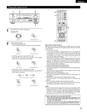
...DTS from a laser disc player. Note that noise will be selected for all input sources other than TUNER. AUTO PCM DTS (Main unit) (Remote control unit) 2 Input mode selection function Different input modes can be generated when you preform the operation to stop playback of signals being input. Select... when DTS signals are being input to the external decoder input jacks are stored in the AUTO mode. Example: CD (Main unit) (Remote control unit) 2 Select the input mode. • Selecting the analog mode Press the ANALOG button to switch to the analog input. (Main unit...
...DTS from a laser disc player. Note that noise will be selected for all input sources other than TUNER. AUTO PCM DTS (Main unit) (Remote control unit) 2 Input mode selection function Different input modes can be generated when you preform the operation to stop playback of signals being input. Select... when DTS signals are being input to the external decoder input jacks are stored in the AUTO mode. Example: CD (Main unit) (Remote control unit) 2 Select the input mode. • Selecting the analog mode Press the ANALOG button to switch to the analog input. (Main unit...

Owners Manual
Page 34
... the channel level is set as follows each time the TONE CONTROL button is displayed on the master volume level display. (Main unit) (Remote control unit) The volume can be output if DTS-compatible CDs or LDs are played in steps of these lights, depending on the tone... to be adjusted selected, turn the SELECT knob. The volume level is pressed. ENGLISH 3 Select the play mode. Example: Stereo (Main unit) (Remote control unit) To select the surround mode while adjusting the surround parameters, tone defeat or tone control, press the surround mode button then operate the...
... the channel level is set as follows each time the TONE CONTROL button is displayed on the master volume level display. (Main unit) (Remote control unit) The volume can be output if DTS-compatible CDs or LDs are played in steps of these lights, depending on the tone... to be adjusted selected, turn the SELECT knob. The volume level is pressed. ENGLISH 3 Select the play mode. Example: Stereo (Main unit) (Remote control unit) To select the surround mode while adjusting the surround parameters, tone defeat or tone control, press the surround mode button then operate the...

Owners Manual
Page 35
...program source to the component connected to check the 2 unit's operating status (Main unit) (Remote control unit) while playing a source by pressing the main unit's DIMMER button repeatedly. (Main unit) (Remote control unit) BRIGHT MEDIUM DIM OFF 1 1 21 35 [2] Listening over headphones 1 Plug ..., 1 the display can be cancelled when MASTER VOL is automatically turned off when headphones are also displayed on (Main unit) (Remote control unit) 1 the display. The display brightness changes in four steps (bright, medium, dim and off the audio output temporarily...
...program source to the component connected to check the 2 unit's operating status (Main unit) (Remote control unit) while playing a source by pressing the main unit's DIMMER button repeatedly. (Main unit) (Remote control unit) BRIGHT MEDIUM DIM OFF 1 1 21 35 [2] Listening over headphones 1 Plug ..., 1 the display can be cancelled when MASTER VOL is automatically turned off when headphones are also displayed on (Main unit) (Remote control unit) 1 the display. The display brightness changes in four steps (bright, medium, dim and off the audio output temporarily...

Owners Manual
Page 36
IN) mode. IN to switch the external input. (Main unit) (Remote control unit) Once this mode. • If the subwoofer output level seems to high, set the "SW ATT." For instructions, refer to "ON". Press the .... 36 IN) setting, press the INPUT MODE (AUTO, PCM, DTS) or ANALOG button to switch to the desired input mode. (See page 33.) (Main unit) (Remote control unit) • When the input mode is set to the recording mode, the same source can be selected. 21 2 1 NOTES: • In play mode...
IN) mode. IN to switch the external input. (Main unit) (Remote control unit) Once this mode. • If the subwoofer output level seems to high, set the "SW ATT." For instructions, refer to "ON". Press the .... 36 IN) setting, press the INPUT MODE (AUTO, PCM, DTS) or ANALOG button to switch to the desired input mode. (See page 33.) (Main unit) (Remote control unit) • When the input mode is set to the recording mode, the same source can be selected. 21 2 1 NOTES: • In play mode...
Owners Manual
Page 37
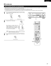
... unit) NOTE: Please make sure the "AUDIO" position of the slide switch on the remote control unit. 3 After completing the adjustment, press the TEST TONE button again. (Remote control unit) 1 1 2 2 2, 3 37 Use the channel volume adjust buttons to adjust the playback level from each surround ... Pro Logic II or Dolby Digital or DTS) modes. (Main unit) 2 Press the TEST TONE button. (Remote control unit) (Remote control unit) Test tones are output from the remote control unit, as (described) below. • The adjustment with the surround function, be performed from the different...
... unit) NOTE: Please make sure the "AUDIO" position of the slide switch on the remote control unit. 3 After completing the adjustment, press the TEST TONE button again. (Remote control unit) 1 1 2 2 2, 3 37 Use the channel volume adjust buttons to adjust the playback level from each surround ... Pro Logic II or Dolby Digital or DTS) modes. (Main unit) 2 Press the TEST TONE button. (Remote control unit) (Remote control unit) Test tones are output from the remote control unit, as (described) below. • The adjustment with the surround function, be performed from the different...
Owners Manual
Page 38
...to suit your tastes, as (described) below. 1 Select the speaker whose level you want to adjust. (Remote control unit) 2 The channel switches as shown below each time the button is pressed. (Remote control unit) FL CNTR FR SR SB SW SL NOTE: Please make sure the "AUDIO" position of the... slide switch on the remote control unit. 3 Adjust the level of the selected speaker. (Remote control unit) Default setting of channel level is 0 ...
...to suit your tastes, as (described) below. 1 Select the speaker whose level you want to adjust. (Remote control unit) 2 The channel switches as shown below each time the button is pressed. (Remote control unit) FL CNTR FR SR SB SW SL NOTE: Please make sure the "AUDIO" position of the... slide switch on the remote control unit. 3 Adjust the level of the selected speaker. (Remote control unit) Default setting of channel level is 0 ...
Owners Manual
Page 39
...TONE DEFEAT SURROUND BACK DEFAULT If you want the bass and trable to be chosen directly by pressing the CINEMA or MUSIC button on the remote control unit during playback in the Dolby Surround Pro Logic II mode. 3 Play a program source with the mark. • For operating... mode switches as shown below each time the button is connected. Display MODE cinema 8 5, 7 4, 6 5, 7 (Main unit) (Remote control unit) To perform this operation from the remote control unit, check that the mode selector switch is set to "AUDIO". 5 Select the optimum mode for the source. 6 Set the surround...
...TONE DEFEAT SURROUND BACK DEFAULT If you want the bass and trable to be chosen directly by pressing the CINEMA or MUSIC button on the remote control unit during playback in the Dolby Surround Pro Logic II mode. 3 Play a program source with the mark. • For operating... mode switches as shown below each time the button is connected. Display MODE cinema 8 5, 7 4, 6 5, 7 (Main unit) (Remote control unit) To perform this operation from the remote control unit, check that the mode selector switch is set to "AUDIO". 5 Select the optimum mode for the source. 6 Set the surround...


