
Service Manual
Page 1
Dell Latitude D400 Service Manual Dell™ Latitude™ D400 Service Manual Before You Begin Preparing to Work Inside the Computer Recommended Tools Computer Orientation Screw Identification Using the Dell Diagnostics When to Use the Dell Diagnostics Features of the Dell Diagnostics Starting the Dell Diagnostics System Components Keyboard Removing the Keyboard Installing the Keyboard Memory Installing a Memory Module Under the Memory Module/Modem...
Dell Latitude D400 Service Manual Dell™ Latitude™ D400 Service Manual Before You Begin Preparing to Work Inside the Computer Recommended Tools Computer Orientation Screw Identification Using the Dell Diagnostics When to Use the Dell Diagnostics Features of the Dell Diagnostics Starting the Dell Diagnostics System Components Keyboard Removing the Keyboard Installing the Keyboard Memory Installing a Memory Module Under the Memory Module/Modem...

Service Manual
Page 13
... testing on your system board, keyboard, hard drive, and display. After the Dell Diagnostics loads and the Main Menu screen appears, click the button for contact information. Using the Dell Diagnostics: NOTE: If you do not need to begin the Dell Diagnostics. When the DELL™ logo appears, press immediately...instructions on the screen to retest the component that appear. Press any key to continue. 6. Press any key to start the Dell Diagnostics from your computer and try again. 5. file:///F|/Service%20Manuals/Dell/Latitude/d400/diag.htm (3 of 5) [2/28/2004 8:06:08 AM]
... testing on your system board, keyboard, hard drive, and display. After the Dell Diagnostics loads and the Main Menu screen appears, click the button for contact information. Using the Dell Diagnostics: NOTE: If you do not need to begin the Dell Diagnostics. When the DELL™ logo appears, press immediately...instructions on the screen to retest the component that appear. Press any key to continue. 6. Press any key to start the Dell Diagnostics from your computer and try again. 5. file:///F|/Service%20Manuals/Dell/Latitude/d400/diag.htm (3 of 5) [2/28/2004 8:06:08 AM]

Service Manual
Page 18
Open the display approximately 180 degrees. 3. file:///F|/Service%20Manuals/Dell/Latitude/d400/keyboard.htm (1 of the center control cover, and pry the cover loose from the bottom case. NOTICE: To avoid electrostatic discharge, ground ...to remove the battery and prepare the computer for work. 2. Follow the instructions in your System Information Guide. Keyboard: Back to Contents Page Keyboard Removing the Keyboard Installing the Keyboard Removing the Keyboard CAUTION: Before performing the following procedures, read the safety instructions in "Preparing to Work Inside the Computer" ...
Open the display approximately 180 degrees. 3. file:///F|/Service%20Manuals/Dell/Latitude/d400/keyboard.htm (1 of the center control cover, and pry the cover loose from the bottom case. NOTICE: To avoid electrostatic discharge, ground ...to remove the battery and prepare the computer for work. 2. Follow the instructions in your System Information Guide. Keyboard: Back to Contents Page Keyboard Removing the Keyboard Installing the Keyboard Removing the Keyboard CAUTION: Before performing the following procedures, read the safety instructions in "Preparing to Work Inside the Computer" ...

Service Manual
Page 19
Keyboard: 1 center control cover 5U447 4. Remove the two M2 x 5-mm screws from the top of the bottom case. Use the pull-tab to pull the keyboard up and out (toward the display) of the keyboard. 5. file:///F|/Service%20Manuals/Dell/Latitude/d400/keyboard.htm (2 of 5) [2/28/2004 8:06:10 AM]
Keyboard: 1 center control cover 5U447 4. Remove the two M2 x 5-mm screws from the top of the bottom case. Use the pull-tab to pull the keyboard up and out (toward the display) of the keyboard. 5. file:///F|/Service%20Manuals/Dell/Latitude/d400/keyboard.htm (2 of 5) [2/28/2004 8:06:10 AM]

Service Manual
Page 20
Keyboard: 1 keyboard P1290 2 keyboard pull-tab 3 M2 x 5-mm screws (2) 1428U 4 securing tabs (5) 6. Pull straight up on the pull-tab that is attached to the keyboard connector to disconnect the connector from the interface connector on the palm rest. 7. Rest the keyboard face down on the system board. file:///F|/Service%20Manuals/Dell/Latitude/d400/keyboard.htm (3 of 5) [2/28/2004 8:06:10 AM]
Keyboard: 1 keyboard P1290 2 keyboard pull-tab 3 M2 x 5-mm screws (2) 1428U 4 securing tabs (5) 6. Pull straight up on the pull-tab that is attached to the keyboard connector to disconnect the connector from the interface connector on the palm rest. 7. Rest the keyboard face down on the system board. file:///F|/Service%20Manuals/Dell/Latitude/d400/keyboard.htm (3 of 5) [2/28/2004 8:06:10 AM]

Service Manual
Page 21
Keyboard: 1 pull-tab on the keyboard into their respective slots in the palm rest. 3. Connect the keyboard connector to the right side so that it down starting on the left side and working to the interface connector on the system board. 2. file:///F|/Service%20Manuals/Dell/Latitude/d400/keyboard.htm (4 of the keyboard. 4. Replace the center control cover and snap it is flush with the palm rest. Replace the two screws at the top of 5) [2/28/2004 8:06:10 AM] Insert the five securing tabs on keyboard connector 2 keyboard connector Installing the Keyboard 1.
Keyboard: 1 pull-tab on the keyboard into their respective slots in the palm rest. 3. Connect the keyboard connector to the right side so that it down starting on the left side and working to the interface connector on the system board. 2. file:///F|/Service%20Manuals/Dell/Latitude/d400/keyboard.htm (4 of the keyboard. 4. Replace the center control cover and snap it is flush with the palm rest. Replace the two screws at the top of 5) [2/28/2004 8:06:10 AM] Insert the five securing tabs on keyboard connector 2 keyboard connector Installing the Keyboard 1.

Service Manual
Page 23
...Memory: Back to Contents Page Memory Installing a Memory Module Under the Memory Module/Modem Cover Installing a Memory Module Under the Keyboard CAUTION: Before performing the following procedures, read the safety instructions in "Preparing to Work Inside the Computer" to the appropriate ... Memory Module Under the Keyboard" Installing a Memory Module Under the Memory Module/Modem Cover 1. Continue to remove the battery and prepare the computer for work. 2. Turn the computer over, loosen the captive screws on the computer. 1. file:///F|/Service%20Manuals/Dell/Latitude/d400/memory.htm (1 of...
...Memory: Back to Contents Page Memory Installing a Memory Module Under the Memory Module/Modem Cover Installing a Memory Module Under the Keyboard CAUTION: Before performing the following procedures, read the safety instructions in "Preparing to Work Inside the Computer" to the appropriate ... Memory Module Under the Keyboard" Installing a Memory Module Under the Memory Module/Modem Cover 1. Continue to remove the battery and prepare the computer for work. 2. Turn the computer over, loosen the captive screws on the computer. 1. file:///F|/Service%20Manuals/Dell/Latitude/d400/memory.htm (1 of...

Service Manual
Page 27
Remove the keyboard. 2. Loosen the two captive screws in the cover labeled "DIMM1." 1 captive screws (2) 2 DIMM1 cover 2X386 3 memory module See Mini RSL file:///F|/Service%20Manuals/Dell/Latitude/d400/memory.htm (5 of 7) [2/28/2004 8:06:11 AM] Memory: Installing a Memory Module Under the Keyboard 1.
Remove the keyboard. 2. Loosen the two captive screws in the cover labeled "DIMM1." 1 captive screws (2) 2 DIMM1 cover 2X386 3 memory module See Mini RSL file:///F|/Service%20Manuals/Dell/Latitude/d400/memory.htm (5 of 7) [2/28/2004 8:06:11 AM] Memory: Installing a Memory Module Under the Keyboard 1.

Service Manual
Page 28
... the memory module connector, do not feel the click, remove the module and reinstall it detects the additional memory and automatically updates file:///F|/Service%20Manuals/Dell/Latitude/d400/memory.htm (6 of the memory module connector until it . Align the notch in the module edge connector with the tab in the connector slot. NOTE... and install the new memory module: a. No error message indicates this failure. 5. Insert the three securing tabs on the DIMM1 cover into place. Replace the keyboard. 7.
... the memory module connector, do not feel the click, remove the module and reinstall it detects the additional memory and automatically updates file:///F|/Service%20Manuals/Dell/Latitude/d400/memory.htm (6 of the memory module connector until it . Align the notch in the module edge connector with the tab in the connector slot. NOTE... and install the new memory module: a. No error message indicates this failure. 5. Insert the three securing tabs on the DIMM1 cover into place. Replace the keyboard. 7.

Service Manual
Page 30
... (such as the back panel) on the computer. 1. Remove the keyboard. 3. If a Mini PCI card is not already installed, go to remove the battery and prepare the computer for work. 2. Disconnect the Mini PCI card from the attached cables. file:///F|/Service%20Manuals/Dell/Latitude/d400/minipci.htm (1 of 4) [2/28/2004 8:06:12 AM] If...
... (such as the back panel) on the computer. 1. Remove the keyboard. 3. If a Mini PCI card is not already installed, go to remove the battery and prepare the computer for work. 2. Disconnect the Mini PCI card from the attached cables. file:///F|/Service%20Manuals/Dell/Latitude/d400/minipci.htm (1 of 4) [2/28/2004 8:06:12 AM] If...

Service Manual
Page 33
Mini PCI Card: 5. Back to the display. 6. Replace the keyboard. Connect the antenna cables to the Mini PCI card, with the white cable in the Mini PCI connector closer to the palm rest, and the black cable in the Mini PCI card connector closer to Contents Page file:///F|/Service%20Manuals/Dell/Latitude/d400/minipci.htm (4 of 4) [2/28/2004 8:06:12 AM]
Mini PCI Card: 5. Back to the display. 6. Replace the keyboard. Connect the antenna cables to the Mini PCI card, with the white cable in the Mini PCI connector closer to the palm rest, and the black cable in the Mini PCI card connector closer to Contents Page file:///F|/Service%20Manuals/Dell/Latitude/d400/minipci.htm (4 of 4) [2/28/2004 8:06:12 AM]
Service Manual
Page 50
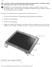
... latch, you must remove the whole bezel. 1. Remove the keyboard. 4. Open the display 180 degrees, and remove the two rubber screw covers, four rubber screw bumpers, and the six M2.5 x 4-mm screws that secure the bezel. 1 rubber screw bumpers 6U549 file:///F|/Service%20Manuals/Dell/Latitude/d400/display.htm (3 of 4) [2/28/2004 8:06:16 AM...
... latch, you must remove the whole bezel. 1. Remove the keyboard. 4. Open the display 180 degrees, and remove the two rubber screw covers, four rubber screw bumpers, and the six M2.5 x 4-mm screws that secure the bezel. 1 rubber screw bumpers 6U549 file:///F|/Service%20Manuals/Dell/Latitude/d400/display.htm (3 of 4) [2/28/2004 8:06:16 AM...

Service Manual
Page 52
... must remove the display assembly before you remove the palm rest; file:///F|/Service%20Manuals/Dell/Latitude/d400/palmrest.htm (1 of the palm rest. 4. Remove the display. 5. Turn the computer over and remove the nine M2.5 x 6-mm screws. Remove the keyboard. Follow the instructions in "Preparing to Work Inside the Computer" to Contents Page Palm...
... must remove the display assembly before you remove the palm rest; file:///F|/Service%20Manuals/Dell/Latitude/d400/palmrest.htm (1 of the palm rest. 4. Remove the display. 5. Turn the computer over and remove the nine M2.5 x 6-mm screws. Remove the keyboard. Follow the instructions in "Preparing to Work Inside the Computer" to Contents Page Palm...

Service Manual
Page 57
... PC Card. 3. Remove the keyboard. 5. Follow the instructions in your System Information Guide. Remove the display. 6. NOTICE: To avoid electrostatic discharge, ground yourself by using a wrist grounding strap or by periodically touching an unpainted metal surface (such as the back panel) on the computer. 1. file:///F|/Service%20Manuals/Dell/Latitude/d400/fan.htm (1 of 2) [2/28...
... PC Card. 3. Remove the keyboard. 5. Follow the instructions in your System Information Guide. Remove the display. 6. NOTICE: To avoid electrostatic discharge, ground yourself by using a wrist grounding strap or by periodically touching an unpainted metal surface (such as the back panel) on the computer. 1. file:///F|/Service%20Manuals/Dell/Latitude/d400/fan.htm (1 of 2) [2/28...


