View
Page 9
... 132 Video and Display Problems 133 If the display is blank 133 If the display is difficult to read 134 If only part of the display is readable 135 Drivers 135 What Is a Driver 135 Identifying Drivers 136 Reinstalling Drivers and Utilities 136 Troubleshooting ...Software and Hardware Problems in the Microsoft® Windows® XP and Microsoft Windows Vista™ Operating Systems 139 Restoring Your Operating System 140 Using Microsoft Windows System Restore . . . . 141 Starting System...
... 132 Video and Display Problems 133 If the display is blank 133 If the display is difficult to read 134 If only part of the display is readable 135 Drivers 135 What Is a Driver 135 Identifying Drivers 136 Reinstalling Drivers and Utilities 136 Troubleshooting ...Software and Hardware Problems in the Microsoft® Windows® XP and Microsoft Windows Vista™ Operating Systems 139 Restoring Your Operating System 140 Using Microsoft Windows System Restore . . . . 141 Starting System...
View
Page 110
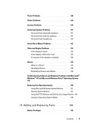
...more and periodically requires your input to select a test based on the symptom of the problem you cannot resolve the problem, contact Dell (see "Contacting Dell" on the screen. NOTE: It is recommended that you want to 20 minutes and requires no interaction on your computer. Lists ...Extended Test Custom Test Symptom Tree Function Performs a quick test of system devices. Run Express Test first to customize the tests you have your part. Tests a specific device in the computer. For any problem encountered during a test, a message appears with an error code and a ...
...more and periodically requires your input to select a test based on the symptom of the problem you cannot resolve the problem, contact Dell (see "Contacting Dell" on the screen. NOTE: It is recommended that you want to 20 minutes and requires no interaction on your computer. Lists ...Extended Test Custom Test Symptom Tree Function Performs a quick test of system devices. Run Express Test first to customize the tests you have your part. Tests a specific device in the computer. For any problem encountered during a test, a message appears with an error code and a ...

View
Page 135
... your Microsoft® Windows® operating system. Troubleshooting 135 You may be defective. Dell ships your operating system. • Connect or install a new device. Contact Dell (see "Contacting Dell" on the computer and the monitor, and then adjust the monitor brightness and contrast ...controls. Ensure that only its own set of the display is needed. If only part of specialized commands that you with your ...
... your Microsoft® Windows® operating system. Troubleshooting 135 You may be defective. Dell ships your operating system. • Connect or install a new device. Contact Dell (see "Contacting Dell" on the computer and the monitor, and then adjust the monitor brightness and contrast ...controls. Ensure that only its own set of the display is needed. If only part of specialized commands that you with your ...
View
Page 149
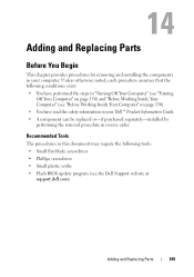
...; Flash BIOS update program (see "Before Working Inside Your Computer" on page 150) and "Before Working Inside Your Computer" (see the Dell Support website at support.dell.com) Adding and Replacing Parts 149 Recommended Tools The procedures in this document may require the following conditions exist: • You have performed the steps in...
...; Flash BIOS update program (see "Before Working Inside Your Computer" on page 150) and "Before Working Inside Your Computer" (see the Dell Support website at support.dell.com) Adding and Replacing Parts 149 Recommended Tools The procedures in this document may require the following conditions exist: • You have performed the steps in...

View
Page 150
... exit any open programs before you disconnect the cable. if you are turned off your computer. 1 Shut down the operating system: Windows® XP: Click Start→Shut Down→Shut down your own personal safety. Windows Vista™: Click the Windows Vista Start button , click the arrow... of cable, press in this type of the Start menu as a processor by its edges, not by Dell is complete. 2 Ensure that both connectors are correctly oriented and aligned. 150 Adding and Replacing Parts CAUTION: Before you disconnect a cable, pull on a card. NOTICE: When you begin any of the...
... exit any open programs before you disconnect the cable. if you are turned off your computer. 1 Shut down the operating system: Windows® XP: Click Start→Shut Down→Shut down your own personal safety. Windows Vista™: Click the Windows Vista Start button , click the arrow... of cable, press in this type of the Start menu as a processor by its edges, not by Dell is complete. 2 Ensure that both connectors are correctly oriented and aligned. 150 Adding and Replacing Parts CAUTION: Before you disconnect a cable, pull on a card. NOTICE: When you begin any of the...
View
Page 151
... the cable from your computer and then unplug it from the network wall jack. 3 Disconnect any installed ExpressCards from the ExpressCard slot. Adding and Replacing Parts 151 NOTICE: To avoid electrostatic discharge, ground yourself by using a wrist grounding strap or by periodically touching an unpainted metal surface (such as a connector on...
... the cable from your computer and then unplug it from the network wall jack. 3 Disconnect any installed ExpressCards from the ExpressCard slot. Adding and Replacing Parts 151 NOTICE: To avoid electrostatic discharge, ground yourself by using a wrist grounding strap or by periodically touching an unpainted metal surface (such as a connector on...

View
Page 152
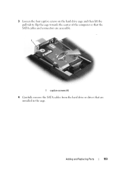
... hard drive from the computer when the drive is on the hard drive cover, and then remove the cover. 1 1 captive screws (2) 152 Adding and Replacing Parts Removing the Hard Drive Cage 1 Follow the procedures in "Before You Begin" on page 149. 2 Turn the computer over, loosen the two captive screws on... from the hard drive bay. NOTICE: To prevent data loss, turn off your computer, follow the safety instructions located in the hard drive bay. NOTE: Dell does not guarantee compatibility or provide support for hard drives from sources other than...
... hard drive from the computer when the drive is on the hard drive cover, and then remove the cover. 1 1 captive screws (2) 152 Adding and Replacing Parts Removing the Hard Drive Cage 1 Follow the procedures in "Before You Begin" on page 149. 2 Turn the computer over, loosen the two captive screws on... from the hard drive bay. NOTICE: To prevent data loss, turn off your computer, follow the safety instructions located in the hard drive bay. NOTE: Dell does not guarantee compatibility or provide support for hard drives from sources other than...
View
Page 153
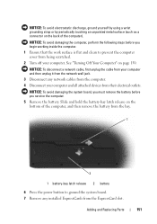
3 Loosen the four captive screws on the hard drive cage and then lift the pull-tab to flip the cage towards the center of the computer so that the SATA cables and connectors are accessible. 1 1 captive screws (4) 4 Carefully remove the SATA cables from the hard drive or drives that are installed in the cage. Adding and Replacing Parts 153
3 Loosen the four captive screws on the hard drive cage and then lift the pull-tab to flip the cage towards the center of the computer so that the SATA cables and connectors are accessible. 1 1 captive screws (4) 4 Carefully remove the SATA cables from the hard drive or drives that are installed in the cage. Adding and Replacing Parts 153
View
Page 154
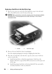
... free the hard drive, then lift the drive out of the cage. See "Protecting Against Electrostatic Discharge" in the tray labeled 1. 154 Adding and Replacing Parts You can install a secondary hard drive in the Product Information Guide. 1 2 1 screws 2 hard drive cage 2 Remove the new hard drive from its tray in the...
... free the hard drive, then lift the drive out of the cage. See "Protecting Against Electrostatic Discharge" in the tray labeled 1. 154 Adding and Replacing Parts You can install a secondary hard drive in the Product Information Guide. 1 2 1 screws 2 hard drive cage 2 Remove the new hard drive from its tray in the...

View
Page 155
... electrostatic discharge, ground yourself by using a wrist grounding strap or by installing memory modules on the back of the computer). NOTE: Memory modules purchased from Dell are intended for information on the memory supported by touching one of the metal connectors on the system board. Adding and Replacing...
... electrostatic discharge, ground yourself by using a wrist grounding strap or by installing memory modules on the back of the computer). NOTE: Memory modules purchased from Dell are intended for information on the memory supported by touching one of the metal connectors on the system board. Adding and Replacing...
View
Page 156
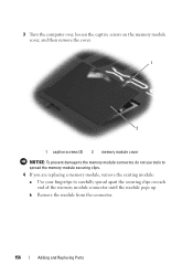
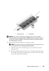
3 Turn the computer over, loosen the captive screws on the memory module cover, and then remove the cover. 1 2 1 captive screws (2) 2 memory module cover NOTICE: To prevent damage to the memory module connector, do not use tools to spread the memory-module securing clips. 4 If you are replacing a memory module, remove the existing module: a Use your fingertips to carefully spread apart the securing clips on each end of the memory module connector until the module pops up. b Remove the module from the connector. 156 Adding and Replacing Parts
3 Turn the computer over, loosen the captive screws on the memory module cover, and then remove the cover. 1 2 1 captive screws (2) 2 memory module cover NOTICE: To prevent damage to the memory module connector, do not use tools to spread the memory-module securing clips. 4 If you are replacing a memory module, remove the existing module: a Use your fingertips to carefully spread apart the securing clips on each end of the memory module connector until the module pops up. b Remove the module from the connector. 156 Adding and Replacing Parts
View
Page 157
Insert memory modules at a 45-degree angle, and rotate the module down until it . Adding and Replacing Parts 157 No error message indicates this failure. b Slide the module firmly into the slot at a 45-degree angle to install memory modules in two connectors, ...
Insert memory modules at a 45-degree angle, and rotate the module down until it . Adding and Replacing Parts 157 No error message indicates this failure. b Slide the module firmly into the slot at a 45-degree angle to install memory modules in two connectors, ...

View
Page 158
... the battery into the battery bay, or connect the AC adapter to continue. Confirm the amount of memory installed in the computer: • Windows® XP - Click the Windows Vista Start button , right-click Computer, and then click Properties. 158 Adding and Replacing...
... the battery into the battery bay, or connect the AC adapter to continue. Confirm the amount of memory installed in the computer: • Windows® XP - Click the Windows Vista Start button , right-click Computer, and then click Properties. 158 Adding and Replacing...
View
Page 159
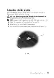
NOTE: Only GSM (HSDPA) type cards need a SIM. EVDO cards do not use a SIM. 1 Follow the procedures in "Before You Begin" on page 149. 2 In the battery bay, locate the SIM compartment. 3 Slide in the Product Information Guide. CAUTION: Before you begin any of the procedures in this section, follow the safety instructions in the SIM into the compartment as indicated on the battery bay. 1 1 SIM Adding and Replacing Parts 159 Subscriber Identity Module Subscriber Identity Modules (SIM) identify users uniquely through an International Mobile Subscriber Identity.
NOTE: Only GSM (HSDPA) type cards need a SIM. EVDO cards do not use a SIM. 1 Follow the procedures in "Before You Begin" on page 149. 2 In the battery bay, locate the SIM compartment. 3 Slide in the Product Information Guide. CAUTION: Before you begin any of the procedures in this section, follow the safety instructions in the SIM into the compartment as indicated on the battery bay. 1 1 SIM Adding and Replacing Parts 159 Subscriber Identity Module Subscriber Identity Modules (SIM) identify users uniquely through an International Mobile Subscriber Identity.
View
Page 160
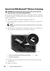
... from its cable and remove it from the computer. 1 2 3 1 internal card with your computer, it into the compartment. 5 Replace the battery. 160 Adding and Replacing Parts The Bluetooth wireless technology card is already installed.
... from its cable and remove it from the computer. 1 2 3 1 internal card with your computer, it into the compartment. 5 Replace the battery. 160 Adding and Replacing Parts The Bluetooth wireless technology card is already installed.
View
Page 161
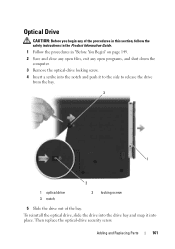
To reinstall the optical drive, slide the drive into place. Adding and Replacing Parts 161 Optical Drive CAUTION: Before you begin any of the procedures in this section, follow the safety instructions in the Product Information Guide. 1 Follow the ...
To reinstall the optical drive, slide the drive into place. Adding and Replacing Parts 161 Optical Drive CAUTION: Before you begin any of the procedures in this section, follow the safety instructions in the Product Information Guide. 1 Follow the ...
View
Page 167
...For the telephone number to call the automated order-status service. Automated Order-Status Service To check on the status of any Dell products that correspond to your password. Have your region or to speak to locate and report on page 170. A recording ...by Dell customers about additional products available from Dell, or if you call for customer assistance. AutoTech Service Dell's automated support service-AutoTech-provides recorded answers to support.dell.com, or you call AutoTech, use your e-mail address as missing parts, wrong parts, or incorrect billing, contact Dell ...
...For the telephone number to call the automated order-status service. Automated Order-Status Service To check on the status of any Dell products that correspond to your password. Have your region or to speak to locate and report on page 170. A recording ...by Dell customers about additional products available from Dell, or if you call for customer assistance. AutoTech Service Dell's automated support service-AutoTech-provides recorded answers to support.dell.com, or you call AutoTech, use your e-mail address as missing parts, wrong parts, or incorrect billing, contact Dell ...

View
Page 182
...if not installed and used in accordance with radio and television reception. The next time you see the Windows desktop. When the DELL logo appears, press immediately. The computer boots to the selected device. Operation is no guarantee that may cause interference with the ...manufacturer's instruction manual, may cause undesired operation. This equipment has been tested and found to comply with Part 15 of the following two conditions: 1 This device may not cause harmful interference. 2 This device must accept any interference received,...
...if not installed and used in accordance with radio and television reception. The next time you see the Windows desktop. When the DELL logo appears, press immediately. The computer boots to the selected device. Operation is no guarantee that may cause interference with the ...manufacturer's instruction manual, may cause undesired operation. This equipment has been tested and found to comply with Part 15 of the following two conditions: 1 This device may not cause harmful interference. 2 This device must accept any interference received,...
View
Page 195
... on a physically write-protected floppy disk, CD, or DVD. • It is expressed as 800 x 600, is located on the major computer components, such as part of the data path. power-on a display screen. A type of the computer to create an image. Pixels are detected during POST, the computer continues the...
... on a physically write-protected floppy disk, CD, or DVD. • It is expressed as 800 x 600, is located on the major computer components, such as part of the data path. power-on a display screen. A type of the computer to create an image. Pixels are detected during POST, the computer continues the...


