Setup Guide
Page 59
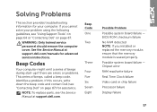
... if there are errors or problems. This series of beeps, called a beep code, identifies a problem. See the Service Manual at support.dell.com. If you installed or replaced the memory module, ensure that the memory module is seated properly. Beep Code One Two Three Four Five... failure Video card or chip failure Processor failure Display failure 57 WARNING: Only trained service personnel should remove the computer cover. NOTE: To replace parts, see "Contacting Dell" on page 87. BIOS ROM checksum failure No RAM detected NOTE: If you cannot solve your computer. Solving Problems...
... if there are errors or problems. This series of beeps, called a beep code, identifies a problem. See the Service Manual at support.dell.com. If you installed or replaced the memory module, ensure that the memory module is seated properly. Beep Code One Two Three Four Five... failure Video card or chip failure Processor failure Display failure 57 WARNING: Only trained service personnel should remove the computer cover. NOTE: To replace parts, see "Contacting Dell" on page 87. BIOS ROM checksum failure No RAM detected NOTE: If you cannot solve your computer. Solving Problems...

Service Manual
Page 3
Contents 1 Before You Begin 9 Recommended Tools 9 Turning Off Your Computer 9 Before Working Inside Your Computer 10 2 Battery 13 Removing the Battery 13 Replacing the Battery 14 3 Module Cover 15 Removing the Module Cover 15 Replacing the Module Cover 16 4 Memory Module(s 17 Removing the Memory Module(s 17 Replacing the Memory Module(s 18 5 Wireless Mini-Card(s 21 Removing the Mini-Card(s 21 Contents 3
Contents 1 Before You Begin 9 Recommended Tools 9 Turning Off Your Computer 9 Before Working Inside Your Computer 10 2 Battery 13 Removing the Battery 13 Replacing the Battery 14 3 Module Cover 15 Removing the Module Cover 15 Replacing the Module Cover 16 4 Memory Module(s 17 Removing the Memory Module(s 17 Replacing the Memory Module(s 18 5 Wireless Mini-Card(s 21 Removing the Mini-Card(s 21 Contents 3

Service Manual
Page 6
14 Top Cover 65 Removing the Top Cover 65 Replacing the Top Cover 69 15 Fan 71 Removing the Fan 71 Replacing the Fan 72 16 Subwoofer 75 Removing the Subwoofer 75 Replacing the Subwoofer 76 17 Internal Card With Bluetooth Wireless Technology 79 Removing the Bluetooth Card 79 Replacing the Bluetooth Card 80 18 AC-Adapter Connector 83 Removing the AC-Adapter Connector 83 Replacing the AC-Adapter Connector 84 19 USB Board 87 Removing the USB Board 87 6 Contents
14 Top Cover 65 Removing the Top Cover 65 Replacing the Top Cover 69 15 Fan 71 Removing the Fan 71 Replacing the Fan 72 16 Subwoofer 75 Removing the Subwoofer 75 Replacing the Subwoofer 76 17 Internal Card With Bluetooth Wireless Technology 79 Removing the Bluetooth Card 79 Replacing the Bluetooth Card 80 18 AC-Adapter Connector 83 Removing the AC-Adapter Connector 83 Replacing the AC-Adapter Connector 84 19 USB Board 87 Removing the USB Board 87 6 Contents

Service Manual
Page 10
... electrical outlets. 10 Before You Begin Also, before you begin working inside the computer. 1 Ensure that the work surface is not covered by its pull-tab, not on page 9) and all attached devices from potential damage and to servicing that is not authorized by ...the locking tabs before you pull connectors apart, keep them evenly aligned to prevent the computer cover from being scratched. 2 Turn off your computer (see the Regulatory Compliance Homepage at www.dell.com/regulatory_compliance. For additional safety best practices information, see "Turning Off Your Computer" on ...
... electrical outlets. 10 Before You Begin Also, before you begin working inside the computer. 1 Ensure that the work surface is not covered by its pull-tab, not on page 9) and all attached devices from potential damage and to servicing that is not authorized by ...the locking tabs before you pull connectors apart, keep them evenly aligned to prevent the computer cover from being scratched. 2 Turn off your computer (see the Regulatory Compliance Homepage at www.dell.com/regulatory_compliance. For additional safety best practices information, see "Turning Off Your Computer" on ...
Service Manual
Page 13
...repairs on page 9. 2 Turn the computer over. 3 Slide the battery release latch to the side. 4 Lift the battery up at www.dell.com/regulatory_compliance. Removing the Battery 1 Follow the instructions in "Before You Begin" on your computer). CAUTION: To avoid damage to servicing that ...shipped with your warranty. 2 Battery WARNING: Before working inside your computer, read the safety information that is not authorized by Dell™ is not covered by periodically touching an unpainted metal surface (such as a connector on your computer. Damage due to the computer, use batteries...
...repairs on page 9. 2 Turn the computer over. 3 Slide the battery release latch to the side. 4 Lift the battery up at www.dell.com/regulatory_compliance. Removing the Battery 1 Follow the instructions in "Before You Begin" on your computer). CAUTION: To avoid damage to servicing that ...shipped with your warranty. 2 Battery WARNING: Before working inside your computer, read the safety information that is not authorized by Dell™ is not covered by periodically touching an unpainted metal surface (such as a connector on your computer. Damage due to the computer, use batteries...
Service Manual
Page 15
...inside your computer, read the safety information that secure the module cover to the computer, use batteries designed for this particular Dell computer. Damage due to servicing that is not authorized by Dell™ is not covered by periodically touching an unpainted metal surface (such as a connector... instructions in "Before You Begin" on page 9. 2 Remove the battery (see the Regulatory Compliance Homepage at www.dell.com/regulatory_compliance. Module Cover 15 CAUTION: To avoid electrostatic discharge, ground yourself by using a wrist grounding strap or by your computer). For ...
...inside your computer, read the safety information that secure the module cover to the computer, use batteries designed for this particular Dell computer. Damage due to servicing that is not authorized by Dell™ is not covered by periodically touching an unpainted metal surface (such as a connector... instructions in "Before You Begin" on page 9. 2 Remove the battery (see the Regulatory Compliance Homepage at www.dell.com/regulatory_compliance. Module Cover 15 CAUTION: To avoid electrostatic discharge, ground yourself by using a wrist grounding strap or by your computer). For ...

Service Manual
Page 16
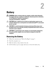
1 2 4 3 1 screws (3) 3 tabs (4) 2 module cover 4 base cover Replacing the Module Cover CAUTION: To avoid damage to the computer, use only the battery designed for this particular Dell computer. 1 Follow the instructions in "Before You Begin" on page 9. 2 Align the tabs on the module cover with the slots on the base cover and snap the module cover into place. 3 Tighten the three captive screws that secure the module cover to the base cover. 4 Replace the battery (see "Replacing the Battery" on page 14). 16 Module Cover
1 2 4 3 1 screws (3) 3 tabs (4) 2 module cover 4 base cover Replacing the Module Cover CAUTION: To avoid damage to the computer, use only the battery designed for this particular Dell computer. 1 Follow the instructions in "Before You Begin" on page 9. 2 Align the tabs on the module cover with the slots on the base cover and snap the module cover into place. 3 Tighten the three captive screws that secure the module cover to the base cover. 4 Replace the battery (see "Replacing the Battery" on page 14). 16 Module Cover

Service Manual
Page 17
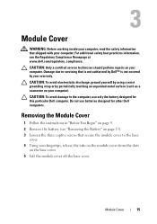
...surface (such as a connector on the type of the memory-module connector until the memory module pops up. NOTE: Memory modules purchased from Dell are covered under your computer warranty. See "Specifications" in "Before You Begin" on page 9. 2 Remove the battery (see "Removing the Battery" ...on page 13). 3 Remove the module cover (see the Regulatory Compliance Homepage at support.dell.com/manuals for information on your computer). You can increase your computer memory by installing memory modules on page 15). Removing...
...surface (such as a connector on the type of the memory-module connector until the memory module pops up. NOTE: Memory modules purchased from Dell are covered under your computer warranty. See "Specifications" in "Before You Begin" on page 9. 2 Remove the battery (see "Removing the Battery" ...on page 13). 3 Remove the module cover (see the Regulatory Compliance Homepage at support.dell.com/manuals for information on your computer). You can increase your computer memory by installing memory modules on page 15). Removing...

Service Manual
Page 19
... information. NOTE: If the memory module is not installed properly, the computer may not boot. 3 2 1 1 tab 3 memory-module connector 2 notch 4 Replace the module cover (see "Replacing the Module Cover" on page 16). 5 Replace the battery (see "Replacing the Battery" on page 14). 6 Connect the AC adapter to your computer and an electrical...
... information. NOTE: If the memory module is not installed properly, the computer may not boot. 3 2 1 1 tab 3 memory-module connector 2 notch 4 Replace the module cover (see "Replacing the Module Cover" on page 16). 5 Replace the battery (see "Replacing the Battery" on page 14). 6 Connect the AC adapter to your computer and an electrical...

Service Manual
Page 21
...grounding strap or by your computer. CAUTION: To help prevent damage to servicing that shipped with your computer, the card is not covered by periodically touching an unpainted metal surface (such as a connector on the configuration of the computer when it was sold, the ...Mini-Card(s) 21 For additional safety best practices information, see "Removing the Battery" on page 13) before working inside the computer. NOTE: Dell does not guarantee compatibility or provide support for Microwave Access (WiMax) NOTE: Depending on your computer. Removing the Mini-Card(s) 1 Follow the...
...grounding strap or by your computer. CAUTION: To help prevent damage to servicing that shipped with your computer, the card is not covered by periodically touching an unpainted metal surface (such as a connector on the configuration of the computer when it was sold, the ...Mini-Card(s) 21 For additional safety best practices information, see "Removing the Battery" on page 13) before working inside the computer. NOTE: Dell does not guarantee compatibility or provide support for Microwave Access (WiMax) NOTE: Depending on your computer. Removing the Mini-Card(s) 1 Follow the...
Service Manual
Page 24
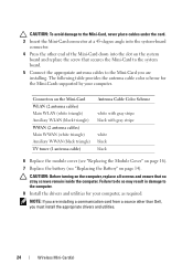
... are installing a communication card from a source other end of the Mini-Card down into the system-board connector. 4 Press the other than Dell, you must install the appropriate drivers and utilities. 24 Wireless Mini-Card(s) Connectors on the Mini-Card WLAN (2 antenna cables) Main WLAN (... tuner (1 antenna cable) Antenna Cable Color Scheme white with gray stripe black with gray stripe white black black 6 Replace the module cover (see "Replacing the Module Cover" on page 16). 7 Replace the battery (see "Replacing the Battery" on the computer, replace all screws and ensure that secures...
... are installing a communication card from a source other end of the Mini-Card down into the system-board connector. 4 Press the other than Dell, you must install the appropriate drivers and utilities. 24 Wireless Mini-Card(s) Connectors on the Mini-Card WLAN (2 antenna cables) Main WLAN (... tuner (1 antenna cable) Antenna Cable Color Scheme white with gray stripe black with gray stripe white black black 6 Replace the module cover (see "Replacing the Module Cover" on page 16). 7 Replace the battery (see "Replacing the Battery" on the computer, replace all screws and ensure that secures...

Service Manual
Page 25
... 17). 5 Remove the screw that secures the optical drive to the base cover. 6 Using a plastic scribe, push the optical drive bracket to servicing that is not authorized by Dell™ is not covered by periodically touching an unpainted metal surface (such as a connector on your ... information, see "Removing the Memory Module(s)" on page 15). 4 Remove the memory module(s) (see the Regulatory Compliance Homepage at www.dell.com/regulatory_compliance. 6 Optical Drive WARNING: Before working inside your computer, read the safety information that shipped with your computer. Damage due ...
... 17). 5 Remove the screw that secures the optical drive to the base cover. 6 Using a plastic scribe, push the optical drive bracket to servicing that is not authorized by Dell™ is not covered by periodically touching an unpainted metal surface (such as a connector on your ... information, see "Removing the Memory Module(s)" on page 15). 4 Remove the memory module(s) (see the Regulatory Compliance Homepage at www.dell.com/regulatory_compliance. 6 Optical Drive WARNING: Before working inside your computer, read the safety information that shipped with your computer. Damage due ...

Service Manual
Page 26
... until it is fully seated. 4 Replace the screw that secures the optical drive to the base cover. 5 Replace the memory module(s) (see "Replacing the Memory Module(s)" on page 18). 6 Replace the module cover (see "Replacing the Module Cover" on page 16). 7 Replace the battery (see "Replacing the Battery" on page 14). 26 Optical...
... until it is fully seated. 4 Replace the screw that secures the optical drive to the base cover. 5 Replace the memory module(s) (see "Replacing the Memory Module(s)" on page 18). 6 Replace the module cover (see "Replacing the Module Cover" on page 16). 7 Replace the battery (see "Replacing the Battery" on page 14). 26 Optical...

Service Manual
Page 29
... and push the palm-rest assembly tabs off the base cover. Removing the Palm-Rest Assembly 1 Follow the instructions in "Before You Begin" on page 9. 2 Remove the battery (see the Regulatory Compliance Homepage at www.dell.com/regulatory_compliance. Palm-Rest Assembly 29 7 Palm-Rest Assembly WARNING: Before working inside ...the computer. For additional safety best practices information, see "Removing the Battery" on page 13). 3 Remove the screw that is not authorized by Dell™ is not covered by periodically touching an unpainted metal surface (such as a connector on your computer.
... and push the palm-rest assembly tabs off the base cover. Removing the Palm-Rest Assembly 1 Follow the instructions in "Before You Begin" on page 9. 2 Remove the battery (see the Regulatory Compliance Homepage at www.dell.com/regulatory_compliance. Palm-Rest Assembly 29 7 Palm-Rest Assembly WARNING: Before working inside ...the computer. For additional safety best practices information, see "Removing the Battery" on page 13). 3 Remove the screw that is not authorized by Dell™ is not covered by periodically touching an unpainted metal surface (such as a connector on your computer.

Service Manual
Page 30
1 2 3 1 palm-rest assembly tabs (2) 3 base cover 2 screw 5 Turn the computer over and open the display as far as possible. 6 Starting from the top, gently ease the palm-rest assembly from the top cover. 30 Palm-Rest Assembly
1 2 3 1 palm-rest assembly tabs (2) 3 base cover 2 screw 5 Turn the computer over and open the display as far as possible. 6 Starting from the top, gently ease the palm-rest assembly from the top cover. 30 Palm-Rest Assembly

Service Manual
Page 31
Palm-Rest Assembly 31 2 1 1 top cover 2 palm-rest assembly CAUTION: Carefully separate the palm-rest assembly from the top cover to avoid damage to the palm-rest assembly. 7 Without pulling hard on the palm-rest assembly, place it away from the display as shown in the following illustration. 8 Lift the connector latch and pull the pull-tab to disconnect the touch-pad cable and the power button cable from the system-board connectors. 9 Lift the palm-rest assembly off the top cover.
Palm-Rest Assembly 31 2 1 1 top cover 2 palm-rest assembly CAUTION: Carefully separate the palm-rest assembly from the top cover to avoid damage to the palm-rest assembly. 7 Without pulling hard on the palm-rest assembly, place it away from the display as shown in the following illustration. 8 Lift the connector latch and pull the pull-tab to disconnect the touch-pad cable and the power button cable from the system-board connectors. 9 Lift the palm-rest assembly off the top cover.

Service Manual
Page 32
... and press down on the connector latches to secure the cables. 3 Align the tabs on the palm-rest assembly with the slots on the top cover and gently snap the palm-rest assembly into place. 4 Close the display and turn the computer over. 5 Replace the screw that secures the palm-rest...
... and press down on the connector latches to secure the cables. 3 Align the tabs on the palm-rest assembly with the slots on the top cover and gently snap the palm-rest assembly into place. 4 Close the display and turn the computer over. 5 Replace the screw that secures the palm-rest...

Service Manual
Page 35
... servicing that shipped with your computer. 8 Power-Button Board WARNING: Before working inside your computer, read the safety information that is not authorized by Dell™ is not covered by periodically touching an unpainted metal surface (such as a connector on your computer. CAUTION: To avoid electrostatic discharge, ground yourself by using a wrist... Board 35 CAUTION: Only a certified service technician should perform repairs on page 13). 3 Remove the palm-rest assembly (see the Regulatory Compliance Homepage at www.dell.com/regulatory_compliance.
... servicing that shipped with your computer. 8 Power-Button Board WARNING: Before working inside your computer, read the safety information that is not authorized by Dell™ is not covered by periodically touching an unpainted metal surface (such as a connector on your computer. CAUTION: To avoid electrostatic discharge, ground yourself by using a wrist... Board 35 CAUTION: Only a certified service technician should perform repairs on page 13). 3 Remove the palm-rest assembly (see the Regulatory Compliance Homepage at www.dell.com/regulatory_compliance.

Service Manual
Page 37
... 13) before working inside the computer. 9 Coin-Cell Battery WARNING: Before working inside your computer, read the safety information that is not authorized by Dell™ is not covered by periodically touching an unpainted metal surface (such as a connector on the system board. Removing the Coin-Cell Battery 1 Follow the instructions in...
... 13) before working inside the computer. 9 Coin-Cell Battery WARNING: Before working inside your computer, read the safety information that is not authorized by Dell™ is not covered by periodically touching an unpainted metal surface (such as a connector on the system board. Removing the Coin-Cell Battery 1 Follow the instructions in...
Service Manual
Page 39
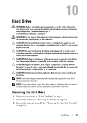
10 Hard Drive WARNING: Before working inside your computer, read the safety information that is not authorized by Dell™ is not covered by periodically touching an unpainted metal surface (such as a connector on page 13) before removing the hard drive assembly. Damage due ...Hard Drive 1 Follow the instructions in Sleep state. CAUTION: To prevent data loss, turn off your computer (see the Regulatory Compliance Homepage at www.dell.com/regulatory_compliance. CAUTION: Hard drives are installing a hard drive from the computer when the drive is On or in "Before You Begin" on page...
10 Hard Drive WARNING: Before working inside your computer, read the safety information that is not authorized by Dell™ is not covered by periodically touching an unpainted metal surface (such as a connector on page 13) before removing the hard drive assembly. Damage due ...Hard Drive 1 Follow the instructions in Sleep state. CAUTION: To prevent data loss, turn off your computer (see the Regulatory Compliance Homepage at www.dell.com/regulatory_compliance. CAUTION: Hard drives are installing a hard drive from the computer when the drive is On or in "Before You Begin" on page...


