Owner's Manual
Page 6
... Floppy Drive 95 Removing a Floppy Drive 96 Installing a Floppy Drive 96 CD/DVD Drive 98 Removing a CD/DVD Drive 98 Installing a CD/DVD Drive 99 Processor Airflow Shroud 102 Removing the Processor Airflow Shroud 102 Installing the Processor Airflow Shroud 103 6 Contents
... Floppy Drive 95 Removing a Floppy Drive 96 Installing a Floppy Drive 96 CD/DVD Drive 98 Removing a CD/DVD Drive 98 Installing a CD/DVD Drive 99 Processor Airflow Shroud 102 Removing the Processor Airflow Shroud 102 Installing the Processor Airflow Shroud 103 6 Contents

Owner's Manual
Page 7
Processor 103 Removing the Processor 103 Installing the Processor 106 Front Panel 108 Removing the Front Panel 108 Replacing the Front Panel 109 Drive Door 110 Removing the Drive Door 110 Replacing the Drive ... Forgotten Passwords 126 Clearing CMOS Settings 127 Cleaning Your Computer 127 Computer, Keyboard, and Monitor 127 Mouse 128 Floppy Drive 128 CDs and DVDs 128 Dell Technical Support Policy (U.S. Only 129 Definition of "Dell-Installed" Software and Peripherals 129 Definition of "Third-Party" Software and Peripherals 129 Contents 7
Processor 103 Removing the Processor 103 Installing the Processor 106 Front Panel 108 Removing the Front Panel 108 Replacing the Front Panel 109 Drive Door 110 Removing the Drive Door 110 Replacing the Drive ... Forgotten Passwords 126 Clearing CMOS Settings 127 Cleaning Your Computer 127 Computer, Keyboard, and Monitor 127 Mouse 128 Floppy Drive 128 CDs and DVDs 128 Dell Technical Support Policy (U.S. Only 129 Definition of "Dell-Installed" Software and Peripherals 129 Definition of "Third-Party" Software and Peripherals 129 Contents 7

Owner's Manual
Page 35
...that is not implemented in system setup to Processors. The second reason is that an overclocked processor, in general, creates excessive heat and electrical fields that Dell's performance labs vigorously test and fine-tune Dell computers at support.dell.com. While many programs can benefit from ...can enable or disable Hyper-Threading through various sources, but Dell discourages and does not support the use the Microsoft® Windows® XP Service Pack 1 (SP1) or later operating system because Windows XP is optimized to attain the best possible overall performance. ...
...that is not implemented in system setup to Processors. The second reason is that an overclocked processor, in general, creates excessive heat and electrical fields that Dell's performance labs vigorously test and fine-tune Dell computers at support.dell.com. While many programs can benefit from ...can enable or disable Hyper-Threading through various sources, but Dell discourages and does not support the use the Microsoft® Windows® XP Service Pack 1 (SP1) or later operating system because Windows XP is optimized to attain the best possible overall performance. ...
Owner's Manual
Page 46
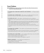
..., move the mouse, or press the power button to the system board (see page 84). I F T H E P O W E R L I G H T I S B L I N K I N G - www.dell.com | support.dell.com Power Problems CAUTION: Before you begin any cards (see page 79). • Remove and then reinstall the graphics card, if applicable (see page... Ensure that the power strip is not receiving power. • Reseat the power cable into an electrical outlet and that the processor power cable is in the Product Information Guide. Also bypass power protection devices, power strips, and power extension cables to verify that...
..., move the mouse, or press the power button to the system board (see page 84). I F T H E P O W E R L I G H T I S B L I N K I N G - www.dell.com | support.dell.com Power Problems CAUTION: Before you begin any cards (see page 79). • Remove and then reinstall the graphics card, if applicable (see page... Ensure that the power strip is not receiving power. • Reseat the power cable into an electrical outlet and that the processor power cable is in the Product Information Guide. Also bypass power protection devices, power strips, and power extension cables to verify that...
Owner's Manual
Page 53
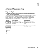
.... Light Pattern ABCD Problem Description Suggested Resolution The computer is in the Product Information Guide. When the computer starts normally, the lights flash. Reinstall the processor (see page 71). Advanced Troubleshooting Diagnostic Lights CAUTION: Before you troubleshoot a problem, your computer has four lights labeled "A," "B," "C," and "D" on the back panel (see page...
.... Light Pattern ABCD Problem Description Suggested Resolution The computer is in the Product Information Guide. When the computer starts normally, the lights flash. Reinstall the processor (see page 71). Advanced Troubleshooting Diagnostic Lights CAUTION: Before you troubleshoot a problem, your computer has four lights labeled "A," "B," "C," and "D" on the back panel (see page...

Owner's Manual
Page 68
Do not touch the components or contacts on your computer. Hold a component such as a processor by its edges, not by touching an unpainted metal surface, such as the metal at the back of the computer. NOTICE: Only a certified service technician ... warranty. Damage due to help protect your computer from potential damage and to servicing that is not authorized by Dell is not covered by its metal mounting bracket. www.dell.com | support.dell.com Before Working Inside Your Computer Use the following steps before you begin any telephone or telecommunication lines from the...
Do not touch the components or contacts on your computer. Hold a component such as a processor by its edges, not by touching an unpainted metal surface, such as the metal at the back of the computer. NOTICE: Only a certified service technician ... warranty. Damage due to help protect your computer from potential damage and to servicing that is not authorized by Dell is not covered by its metal mounting bracket. www.dell.com | support.dell.com Before Working Inside Your Computer Use the following steps before you begin any telephone or telecommunication lines from the...

Owner's Manual
Page 71
... network or broadband device. Do not block the vents. 2 cover latch release To open the computer, lay the computer on all computers 1 processor fans (2) For optimal cooling, two processor fans are provided. If you use the connector on page 73. 3 network adapter connector To attach your computer to a network or broadband device...
... network or broadband device. Do not block the vents. 2 cover latch release To open the computer, lay the computer on all computers 1 processor fans (2) For optimal cooling, two processor fans are provided. If you use the connector on page 73. 3 network adapter connector To attach your computer to a network or broadband device...

Owner's Manual
Page 74
www.dell.com | support.dell.com Inside View of Your Computer floppy drive CD/DVD drive processor airflow shroud hard drive shroud PCI card shroud and fan processor fan power supply fans (2) system board power supply 74 Removing and Installing Parts
www.dell.com | support.dell.com Inside View of Your Computer floppy drive CD/DVD drive processor airflow shroud hard drive shroud PCI card shroud and fan processor fan power supply fans (2) system board power supply 74 Removing and Installing Parts
Owner's Manual
Page 75
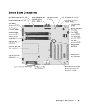
... Components hard-drive connector (PRI_IDE) floppy-drive connector (FLOPPY) main power connector (PWR) auxiliary power LED (AUX_PWR) memory module connectors (2, 4) memory module connectors (1, 3) processor fan (CPU FAN) processor and heatsink connector serial ATA connectors (SATA-0, SATA-1, SATA-2, SATA-3) password jumper (PASS) SCSI LED header (SCSI LED) front-panel connector (FRONT PANEL) internal...
... Components hard-drive connector (PRI_IDE) floppy-drive connector (FLOPPY) main power connector (PWR) auxiliary power LED (AUX_PWR) memory module connectors (2, 4) memory module connectors (1, 3) processor fan (CPU FAN) processor and heatsink connector serial ATA connectors (SATA-0, SATA-1, SATA-2, SATA-3) password jumper (PASS) SCSI LED header (SCSI LED) front-panel connector (FRONT PANEL) internal...
Owner's Manual
Page 76
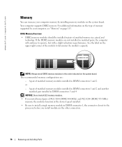
www.dell.com | support.dell.com Memory You can increase your computer, see "Memory" on page 115. DDR2 Memory Overview • DDR2 memory modules should be installed in pairs of ...; If you install modules in DIMM connectors 1 and 2 or - The recommended memory configurations are not installed in matched pairs, the computer will continue to the processor, before you install mixed pairs of matched memory modules installed in the other connectors. 76 Removing and Installing Parts A pair of PC2-3200 (DDR2 400...
www.dell.com | support.dell.com Memory You can increase your computer, see "Memory" on page 115. DDR2 Memory Overview • DDR2 memory modules should be installed in pairs of ...; If you install modules in DIMM connectors 1 and 2 or - The recommended memory configurations are not installed in matched pairs, the computer will continue to the processor, before you install mixed pairs of matched memory modules installed in the other connectors. 76 Removing and Installing Parts A pair of PC2-3200 (DDR2 400...

Owner's Manual
Page 78
If you apply equal force to processor securing clips (2) connector 4 Align the notch on the bottom of the module with the crossbar in the connector. notch memory module cutouts (2) crossbar NOTICE: To ... module. 5 Insert the module into the connector until the module snaps into position. memory connector closest to each end of the memory module connector. www.dell.com | support.dell.com 3 Press out the securing clip at each end of the module. 78 Removing and Installing Parts
If you apply equal force to processor securing clips (2) connector 4 Align the notch on the bottom of the module with the crossbar in the connector. notch memory module cutouts (2) crossbar NOTICE: To ... module. 5 Insert the module into the connector until the module snaps into position. memory connector closest to each end of the memory module connector. www.dell.com | support.dell.com 3 Press out the securing clip at each end of the module. 78 Removing and Installing Parts

Owner's Manual
Page 102
www.dell.com | support.dell.com Processor Airflow Shroud Removing the Processor Airflow Shroud CAUTION: Before you touch any of the computer. 3 Lift the shroud up to components inside your computer, discharge static electricity from your computer's ...
www.dell.com | support.dell.com Processor Airflow Shroud Removing the Processor Airflow Shroud CAUTION: Before you touch any of the computer. 3 Lift the shroud up to components inside your computer, discharge static electricity from your computer's ...

Owner's Manual
Page 103
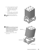
... tabs snap securely into the computer. 5 Connect your system board. Installing the Processor Airflow Shroud 1 Attach both fan power cables to electrical outlets, and turn them on. Processor Removing the Processor NOTICE: Do not perform the following steps unless you begin any of the procedures...(see "System Board Components" on page 75) on the system board. 3 Disconnect the power cable from the 12V PWR connector (see "Dell Technical Support Policy (U.S. Removing and Installing Parts 103 Only)" on the system board. 2 Align the anchor tabs with hardware removal and replacement....
... tabs snap securely into the computer. 5 Connect your system board. Installing the Processor Airflow Shroud 1 Attach both fan power cables to electrical outlets, and turn them on. Processor Removing the Processor NOTICE: Do not perform the following steps unless you begin any of the procedures...(see "System Board Components" on page 75) on the system board. 3 Disconnect the power cable from the 12V PWR connector (see "Dell Technical Support Policy (U.S. Removing and Installing Parts 103 Only)" on the system board. 2 Align the anchor tabs with hardware removal and replacement....
Owner's Manual
Page 105
Press on the socket release lever. NOTICE: If you are installing a processor upgrade kit from Dell, reuse the original heat sink and blower when you are not installing a processor upgrade kit from Dell, discard the original heat sink. If you install your new processor. 6 Push down on the second retention tab while lifting the heat sink...
Press on the socket release lever. NOTICE: If you are installing a processor upgrade kit from Dell, reuse the original heat sink and blower when you are not installing a processor upgrade kit from Dell, discard the original heat sink. If you install your new processor. 6 Push down on the second retention tab while lifting the heat sink...

Owner's Manual
Page 106
... unpainted metal surface on the socket is ready for the new processor. NOTICE: You must position the processor correctly in the release position so that the socket is not fully extended, move it to the processor and the computer when you turn on the computer. 2 If...lever on the back of the computer. 1 Unpack the new processor. Leave the release lever extended in the socket to avoid permanent damage to that position. 106 Removing and Installing Parts processor cover processor socket release lever 8 Remove the processor from the socket. www.dell.com | support.dell.com 7 Open the...
... unpainted metal surface on the socket is ready for the new processor. NOTICE: You must position the processor correctly in the release position so that the socket is not fully extended, move it to the processor and the computer when you turn on the computer. 2 If...lever on the back of the computer. 1 Unpack the new processor. Leave the release lever extended in the socket to avoid permanent damage to that position. 106 Removing and Installing Parts processor cover processor socket release lever 8 Remove the processor from the socket. www.dell.com | support.dell.com 7 Open the...

Owner's Manual
Page 107
... socket, and do not use excessive force when you install the process. If you installed a processor replacement kit from Dell, reuse the original heat sink assembly when you are delicate. 3 Align the pin-1 corners of the processor and socket. Be careful not to touch or bend the pins on the system board. 4 Set...
... socket, and do not use excessive force when you install the process. If you installed a processor replacement kit from Dell, reuse the original heat sink assembly when you are delicate. 3 Align the pin-1 corners of the processor and socket. Be careful not to touch or bend the pins on the system board. 4 Set...
Owner's Manual
Page 115
...24 4-Mb Integrated network interface capable of memory available to verify the amount of 10/100/1000 communication. 800- Appendix Specifications Processor Processor type Cache Memory Type Memory connectors Memory capacities Minimum memory Maximum memory BIOS address Computer Information Chipset DMA channels Interrupt levels BIOS... chip (NVRAM) NIC System clock Video Type Intel® Pentium® 4 with HT Technology NOTE: Not all Pentium 4 processors support Hyper-Threading technology. 512 KB, 1 MB, or 2 MB 400- and 533-MHz DDR2 unbuffered SDRAM four 256 MB, 512 MB,...
...24 4-Mb Integrated network interface capable of memory available to verify the amount of 10/100/1000 communication. 800- Appendix Specifications Processor Processor type Cache Memory Type Memory connectors Memory capacities Minimum memory Maximum memory BIOS address Computer Information Chipset DMA channels Interrupt levels BIOS... chip (NVRAM) NIC System clock Video Type Intel® Pentium® 4 with HT Technology NOTE: Not all Pentium 4 processors support Hyper-Threading technology. 512 KB, 1 MB, or 2 MB 400- and 533-MHz DDR2 unbuffered SDRAM four 256 MB, 512 MB,...

Owner's Manual
Page 121
Identifies whether the computer's processor supports Hyper-Threading and lists the processor bus speed, processor ID, clock speed, and L2 cache. You can set the SATA controller to press . If a boot routine is active (available only for booting from a USB ...
Identifies whether the computer's processor supports Hyper-Threading and lists the processor bus speed, processor ID, clock speed, and L2 cache. You can set the SATA controller to press . If a boot routine is active (available only for booting from a USB ...

Owner's Manual
Page 122
...for the parallel port. The hard drive operates at its maximum speed. NOTE: Changing the acoustics setting does not alter your computer's processor supports Hyper-Threading, this option appears in the same way that access to Off, AT, PS/2, EPP, or ECP. Identifies and... defines the parallel port DMA settings. Auto, the default setting, automatically configures a connector to be assigned and verified. www.dell.com | support.dell.com LPT Port Mode LPT Port Address LPT Port DMA Serial Port #1 Video Primary Video Performance HyperThreading Performance Security Admin Password System...
...for the parallel port. The hard drive operates at its maximum speed. NOTE: Changing the acoustics setting does not alter your computer's processor supports Hyper-Threading, this option appears in the same way that access to Off, AT, PS/2, EPP, or ECP. Identifies and... defines the parallel port DMA settings. Auto, the default setting, automatically configures a connector to be assigned and verified. www.dell.com | support.dell.com LPT Port Mode LPT Port Address LPT Port DMA Serial Port #1 Video Primary Video Performance HyperThreading Performance Security Admin Password System...

Owner's Manual
Page 150
... e-mail problems, 39 End User License Agreement, 10 ergonomics information, 10 error messages, 40 diagnostic lights, 53 F fans power supply, 72 processor, 71 Files and Settings Transfer Wizard, 26 Finding Information, 9 floppy drive installing, 96 removing, 95 H hard drive activity light, 69 installing..., 91 installing second, 94 problems, 39 removing, 90 hardware Dell Diagnostics, 56 drives, RAID configuration, 17 Hardware Troubleshooter, 64 headphone connector, 70 Help and Support Center, 11 help file Windows Help ...
... e-mail problems, 39 End User License Agreement, 10 ergonomics information, 10 error messages, 40 diagnostic lights, 53 F fans power supply, 72 processor, 71 Files and Settings Transfer Wizard, 26 Finding Information, 9 floppy drive installing, 96 removing, 95 H hard drive activity light, 69 installing..., 91 installing second, 94 problems, 39 removing, 90 hardware Dell Diagnostics, 56 drives, RAID configuration, 17 Hardware Troubleshooter, 64 headphone connector, 70 Help and Support Center, 11 help file Windows Help ...


