Owner's Manual
Page 6
... Floppy Drive 95 Removing a Floppy Drive 96 Installing a Floppy Drive 96 CD/DVD Drive 98 Removing a CD/DVD Drive 98 Installing a CD/DVD Drive 99 Processor Airflow Shroud 102 Removing the Processor Airflow Shroud 102 Installing the Processor Airflow Shroud 103 6 Contents
... Floppy Drive 95 Removing a Floppy Drive 96 Installing a Floppy Drive 96 CD/DVD Drive 98 Removing a CD/DVD Drive 98 Installing a CD/DVD Drive 99 Processor Airflow Shroud 102 Removing the Processor Airflow Shroud 102 Installing the Processor Airflow Shroud 103 6 Contents

Owner's Manual
Page 7
Only 129 Definition of "Dell-Installed" Software and Peripherals 129 Definition of "Third-Party" Software and Peripherals 129 Contents 7 Processor 103 Removing the Processor 103 Installing the Processor 106 Front Panel 108 Removing the Front Panel 108 Replacing the Front Panel 109 Drive Door 110 Removing the Drive Door 110 Replacing the Drive ... Forgotten Passwords 126 Clearing CMOS Settings 127 Cleaning Your Computer 127 Computer, Keyboard, and Monitor 127 Mouse 128 Floppy Drive 128 CDs and DVDs 128 Dell Technical Support Policy (U.S.
Only 129 Definition of "Dell-Installed" Software and Peripherals 129 Definition of "Third-Party" Software and Peripherals 129 Contents 7 Processor 103 Removing the Processor 103 Installing the Processor 106 Front Panel 108 Removing the Front Panel 108 Replacing the Front Panel 109 Drive Door 110 Removing the Drive Door 110 Replacing the Drive ... Forgotten Passwords 126 Clearing CMOS Settings 127 Cleaning Your Computer 127 Computer, Keyboard, and Monitor 127 Mouse 128 Floppy Drive 128 CDs and DVDs 128 Dell Technical Support Policy (U.S.

Owner's Manual
Page 35
...can enable or disable Hyper-Threading through various sources, but Dell discourages and does not support the use the Microsoft® Windows® XP Service Pack 1 (SP1) or later operating system because Windows XP is optimized to take advantage of Hyper-Threading technology. The ... can benefit from the software manufacturer. The second reason is that an overclocked processor, in an attempt to attain the best possible overall performance. Overclocking Dell locks the processor multiplier options in the labs could cause performance degradation. Optimizing Performance 35 There are...
...can enable or disable Hyper-Threading through various sources, but Dell discourages and does not support the use the Microsoft® Windows® XP Service Pack 1 (SP1) or later operating system because Windows XP is optimized to take advantage of Hyper-Threading technology. The ... can benefit from the software manufacturer. The second reason is that an overclocked processor, in an attempt to attain the best possible overall performance. Overclocking Dell locks the processor multiplier options in the labs could cause performance degradation. Optimizing Performance 35 There are...
Owner's Manual
Page 46
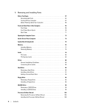
...Remove and then reinstall any of interference are securely connected to match the AC power at your location (if applicable). • Ensure that the processor power cable is in the Product Information Guide. See "Diagnostic Lights" on the keyboard, move the mouse, or press the power button to ... board (see page 84). Some possible causes of the procedures in this section, follow the safety instructions located in standby mode. www.dell.com | support.dell.com Power Problems CAUTION: Before you begin any cards (see page 79). • Remove and then reinstall the graphics card, if ...
...Remove and then reinstall any of interference are securely connected to match the AC power at your location (if applicable). • Ensure that the processor power cable is in the Product Information Guide. See "Diagnostic Lights" on the keyboard, move the mouse, or press the power button to ... board (see page 84). Some possible causes of the procedures in this section, follow the safety instructions located in standby mode. www.dell.com | support.dell.com Power Problems CAUTION: Before you begin any cards (see page 79). • Remove and then reinstall the graphics card, if ...
Owner's Manual
Page 53
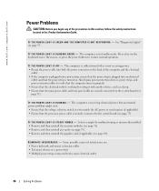
..., the color and sequence of the procedures in this section, follow the safety instructions located in a normal off Advanced Troubleshooting 53 Reinstall the processor (see page 71). ABCD A possible processor failure has occurred. The lights can be yellow or green. Advanced Troubleshooting Diagnostic Lights CAUTION: Before you troubleshoot a problem, your computer has...
..., the color and sequence of the procedures in this section, follow the safety instructions located in a normal off Advanced Troubleshooting 53 Reinstall the processor (see page 71). ABCD A possible processor failure has occurred. The lights can be yellow or green. Advanced Troubleshooting Diagnostic Lights CAUTION: Before you troubleshoot a problem, your computer has...

Owner's Manual
Page 68
...press in the Product Information Guide. NOTICE: Before touching anything inside the computer. 1 Turn off your computer (see page 73). www.dell.com | support.dell.com Before Working Inside Your Computer Use the following steps before opening the cover. 4 Open the computer cover (see page 67). Also...CAUTION: Before you begin working inside your computer, ground yourself by its edges or by touching an unpainted metal surface, such as a processor by its strain-relief loop, not on its edges, not by your computer from the electrical outlet before you work, periodically touch an...
...press in the Product Information Guide. NOTICE: Before touching anything inside the computer. 1 Turn off your computer (see page 73). www.dell.com | support.dell.com Before Working Inside Your Computer Use the following steps before opening the cover. 4 Open the computer cover (see page 67). Also...CAUTION: Before you begin working inside your computer, ground yourself by its edges or by touching an unpainted metal surface, such as a processor by its strain-relief loop, not on its edges, not by your computer from the electrical outlet before you work, periodically touch an...

Owner's Manual
Page 71
... network speed to 10 Mbps to ensure reliable operation. 4 TV-OUT connector Connects your computer to the network adapter connector on all computers 1 processor fans (2) For optimal cooling, two processor fans are provided. A click indicates that you must use Category 5 wiring and connectors for your network. Back View 12 1 13 14 2 15...
... network speed to 10 Mbps to ensure reliable operation. 4 TV-OUT connector Connects your computer to the network adapter connector on all computers 1 processor fans (2) For optimal cooling, two processor fans are provided. A click indicates that you must use Category 5 wiring and connectors for your network. Back View 12 1 13 14 2 15...

Owner's Manual
Page 74
www.dell.com | support.dell.com Inside View of Your Computer floppy drive CD/DVD drive processor airflow shroud hard drive shroud PCI card shroud and fan processor fan power supply fans (2) system board power supply 74 Removing and Installing Parts
www.dell.com | support.dell.com Inside View of Your Computer floppy drive CD/DVD drive processor airflow shroud hard drive shroud PCI card shroud and fan processor fan power supply fans (2) system board power supply 74 Removing and Installing Parts
Owner's Manual
Page 75
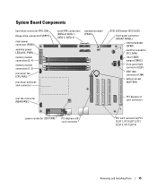
... Components hard-drive connector (PRI_IDE) floppy-drive connector (FLOPPY) main power connector (PWR) auxiliary power LED (AUX_PWR) memory module connectors (2, 4) memory module connectors (1, 3) processor fan (CPU FAN) processor and heatsink connector serial ATA connectors (SATA-0, SATA-1, SATA-2, SATA-3) password jumper (PASS) SCSI LED header (SCSI LED) front-panel connector (FRONT PANEL) internal...
... Components hard-drive connector (PRI_IDE) floppy-drive connector (FLOPPY) main power connector (PWR) auxiliary power LED (AUX_PWR) memory module connectors (2, 4) memory module connectors (1, 3) processor fan (CPU FAN) processor and heatsink connector serial ATA connectors (SATA-0, SATA-1, SATA-2, SATA-3) password jumper (PASS) SCSI LED header (SCSI LED) front-panel connector (FRONT PANEL) internal...
Owner's Manual
Page 76
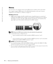
... installed in DIMM connector 1, the connector closest to determine the module's capacity. See the label on the upper-right corner of the module to the processor, before you install mixed pairs of matched memory modules installed in DIMM connectors 1 and 2 and another matched pair installed in DIMM connectors 3 and 4 NOTICE: Do... 533-MHz) memory, the modules function at the slowest speed installed. • Be sure to install a single memory module in DIMM connectors 1 and 2 or - www.dell.com | support.dell.com Memory You can increase your computer, see "Memory" on page 115.
... installed in DIMM connector 1, the connector closest to determine the module's capacity. See the label on the upper-right corner of the module to the processor, before you install mixed pairs of matched memory modules installed in DIMM connectors 1 and 2 and another matched pair installed in DIMM connectors 3 and 4 NOTICE: Do... 533-MHz) memory, the modules function at the slowest speed installed. • Be sure to install a single memory module in DIMM connectors 1 and 2 or - www.dell.com | support.dell.com Memory You can increase your computer, see "Memory" on page 115.

Owner's Manual
Page 78
... end of the module. 78 Removing and Installing Parts If you apply equal force to processor securing clips (2) connector 4 Align the notch on the bottom of the module with the crossbar in the connector. www.dell.com | support.dell.com 3 Press out the securing clip at each end of the memory module connector.
... end of the module. 78 Removing and Installing Parts If you apply equal force to processor securing clips (2) connector 4 Align the notch on the bottom of the module with the crossbar in the connector. www.dell.com | support.dell.com 3 Press out the securing clip at each end of the memory module connector.

Owner's Manual
Page 102
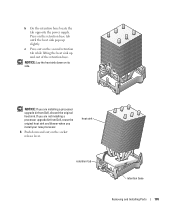
... too quickly. 1 Follow the procedures in the Product Information Guide. shroud release lever anchor tabs (3) 102 Removing and Installing Parts www.dell.com | support.dell.com Processor Airflow Shroud Removing the Processor Airflow Shroud CAUTION: Before you touch any of the computer. 3 Lift the shroud up to components inside your computer, discharge static electricity...
... too quickly. 1 Follow the procedures in the Product Information Guide. shroud release lever anchor tabs (3) 102 Removing and Installing Parts www.dell.com | support.dell.com Processor Airflow Shroud Removing the Processor Airflow Shroud CAUTION: Before you touch any of the computer. 3 Lift the shroud up to components inside your computer, discharge static electricity...

Owner's Manual
Page 103
...a network cable, first plug the cable into the network wall jack and then plug it into place. 4 Close the computer cover. Processor Removing the Processor NOTICE: Do not perform the following steps unless you begin any of the procedures in this section, follow the safety instructions located in the...FAN1 connector (see "System Board Components" on page 75) on the system board. 3 Disconnect the power cable from the 12V PWR connector (see "Dell Technical Support Policy (U.S. Only)" on . CAUTION: Before you are familiar with the securing slots. 3 Gently press the shroud until the anchor tabs ...
...a network cable, first plug the cable into the network wall jack and then plug it into place. 4 Close the computer cover. Processor Removing the Processor NOTICE: Do not perform the following steps unless you begin any of the procedures in this section, follow the safety instructions located in the...FAN1 connector (see "System Board Components" on page 75) on the system board. 3 Disconnect the power cable from the 12V PWR connector (see "Dell Technical Support Policy (U.S. Only)" on . CAUTION: Before you are familiar with the securing slots. 3 Gently press the shroud until the anchor tabs ...
Owner's Manual
Page 105
...on the socket release lever. NOTICE: If you install your new processor. 6 Push down on the retention base tab until the heat sink pops up and out of the retention base. If you are installing a processor upgrade kit from Dell, reuse the original heat sink and blower when you are not installing... a processor upgrade kit from Dell, discard the original heat sink. NOTICE: Lay the heat sink down and out on the...
...on the socket release lever. NOTICE: If you install your new processor. 6 Push down on the retention base tab until the heat sink pops up and out of the retention base. If you are installing a processor upgrade kit from Dell, reuse the original heat sink and blower when you are not installing... a processor upgrade kit from Dell, discard the original heat sink. NOTICE: Lay the heat sink down and out on the...

Owner's Manual
Page 106
... it to that the socket is ready for the new processor. NOTICE: You must position the processor correctly in the release position so that position. 106 Removing and Installing Parts www.dell.com | support.dell.com 7 Open the processor cover. processor cover processor socket release lever 8 Remove the processor from the socket. Leave the release lever extended in...
... it to that the socket is ready for the new processor. NOTICE: You must position the processor correctly in the release position so that position. 106 Removing and Installing Parts www.dell.com | support.dell.com 7 Open the processor cover. processor cover processor socket release lever 8 Remove the processor from the socket. Leave the release lever extended in...

Owner's Manual
Page 107
... are not installing a processor upgrade kit from Dell, return the original heat sink assembly and processor to touch or bend the pins on the system board. 4 Set the processor lightly in which your replacement kit was sent. If you installed a processor replacement kit from Dell, reuse the original heat... sink assembly when you replace the processor. Be careful not to Dell in the same package in the socket and...
... are not installing a processor upgrade kit from Dell, return the original heat sink assembly and processor to touch or bend the pins on the system board. 4 Set the processor lightly in which your replacement kit was sent. If you installed a processor replacement kit from Dell, reuse the original heat... sink assembly when you replace the processor. Be careful not to Dell in the same package in the socket and...
Owner's Manual
Page 115
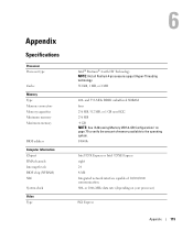
...Information Chipset DMA channels Interrupt levels BIOS chip (NVRAM) NIC System clock Video Type Intel® Pentium® 4 with HT Technology NOTE: Not all Pentium 4 processors support Hyper-Threading technology. 512 KB, 1 MB, or 2 MB 400- and 533-MHz DDR2 unbuffered SDRAM four 256 MB, 512 MB, or 1 GB... non-ECC 256 MB 4 GB NOTE: See "Addressing Memory With 4-GB Configurations" on your processor) PCI Express Appendix 115 F0000h Intel 925X Express or Intel 925XE Express eight 24 4-Mb Integrated network interface capable of memory available to verify the...
...Information Chipset DMA channels Interrupt levels BIOS chip (NVRAM) NIC System clock Video Type Intel® Pentium® 4 with HT Technology NOTE: Not all Pentium 4 processors support Hyper-Threading technology. 512 KB, 1 MB, or 2 MB 400- and 533-MHz DDR2 unbuffered SDRAM four 256 MB, 512 MB, or 1 GB... non-ECC 256 MB 4 GB NOTE: See "Addressing Memory With 4-GB Configurations" on your processor) PCI Express Appendix 115 F0000h Intel 925X Express or Intel 925XE Express eight 24 4-Mb Integrated network interface capable of memory available to verify the...

Owner's Manual
Page 121
.... Identifies and defines the floppy drive attached to boot from the sequence of memory installed. Appendix 121 Identifies whether the computer's processor supports Hyper-Threading and lists the processor bus speed, processor ID, clock speed, and L2 cache. If a boot routine is active (available only for RAID. To boot from a network server. The...
.... Identifies and defines the floppy drive attached to boot from the sequence of memory installed. Appendix 121 Identifies whether the computer's processor supports Hyper-Threading and lists the processor bus speed, processor ID, clock speed, and L2 cache. If a boot routine is active (available only for RAID. To boot from a network server. The...

Owner's Manual
Page 122
...at its maximum speed. This section displays available system security options. NOTE: Changing the acoustics setting does not alter your computer's processor supports Hyper-Threading, this option appears in the same way that access to the system can set the parallel port to the computer...'s system setup program in the Options List. • Bypass - Identifies the address for the parallel port. www.dell.com | support.dell.com LPT Port Mode LPT Port Address LPT Port DMA Serial Port #1 Video Primary Video Performance HyperThreading Performance Security Admin Password ...
...at its maximum speed. This section displays available system security options. NOTE: Changing the acoustics setting does not alter your computer's processor supports Hyper-Threading, this option appears in the same way that access to the system can set the parallel port to the computer...'s system setup program in the Options List. • Bypass - Identifies the address for the parallel port. www.dell.com | support.dell.com LPT Port Mode LPT Port Address LPT Port DMA Serial Port #1 Video Primary Video Performance HyperThreading Performance Security Admin Password ...

Owner's Manual
Page 150
... e-mail problems, 39 End User License Agreement, 10 ergonomics information, 10 error messages, 40 diagnostic lights, 53 F fans power supply, 72 processor, 71 Files and Settings Transfer Wizard, 26 Finding Information, 9 floppy drive installing, 96 removing, 95 H hard drive activity light, 69 installing..., 91 installing second, 94 problems, 39 removing, 90 hardware Dell Diagnostics, 56 drives, RAID configuration, 17 Hardware Troubleshooter, 64 headphone connector, 70 Help and Support Center, 11 help file Windows Help ...
... e-mail problems, 39 End User License Agreement, 10 ergonomics information, 10 error messages, 40 diagnostic lights, 53 F fans power supply, 72 processor, 71 Files and Settings Transfer Wizard, 26 Finding Information, 9 floppy drive installing, 96 removing, 95 H hard drive activity light, 69 installing..., 91 installing second, 94 problems, 39 removing, 90 hardware Dell Diagnostics, 56 drives, RAID configuration, 17 Hardware Troubleshooter, 64 headphone connector, 70 Help and Support Center, 11 help file Windows Help ...


