
Dell™ Technology Guide
Page 207
...your front speaker cable to the right audio out/headphone connector. Setting up the 5.1 Audio Connections To set up the 5.1 audio connections: Click Start →Control Panel→Additional Options. In the Jacks tab, there are three connector icons. while the 1 refers to the five main audio... front, center front, right front, left surround and right surround; Run IDT Audio Control Panel. A 5.1 signal can be supported on all computers. 5.1 refers to the number of audio channels in /microphone connector. 2 Click the middle headphone icon, select Device: Center/LFE Speaker, and plug your ...
...your front speaker cable to the right audio out/headphone connector. Setting up the 5.1 Audio Connections To set up the 5.1 audio connections: Click Start →Control Panel→Additional Options. In the Jacks tab, there are three connector icons. while the 1 refers to the five main audio... front, center front, right front, left surround and right surround; Run IDT Audio Control Panel. A 5.1 signal can be supported on all computers. 5.1 refers to the number of audio channels in /microphone connector. 2 Click the middle headphone icon, select Device: Center/LFE Speaker, and plug your ...

Dell™ Technology Guide
Page 218
... you to connect an external DVI-compatible monitor, such as flat-panel monitors or TVs. Connector Description/Function A DVI connector allows you to connect an external HDMI-compatible monitor or TV. Cables for audio because the DVI connector does not transmit the audio signal. NOTE: DVI and HDMI are compatible and there are unique...
... you to connect an external DVI-compatible monitor, such as flat-panel monitors or TVs. Connector Description/Function A DVI connector allows you to connect an external HDMI-compatible monitor or TV. Cables for audio because the DVI connector does not transmit the audio signal. NOTE: DVI and HDMI are compatible and there are unique...

Dell™ Technology Guide
Page 250
... video card and TV display resolution. Use this same control panel to adjust display resolution. 250 Connecting Your Computer to set ... Resolution is Blurry Use the control panel for the video card vendor to a TV and Adjusting Display Settings TV Colors are using the correct connectors on the back of the TV... and the computer, reconnect the video cable to the computer and the TV. 5 Turn on the Display Properties menu. This method provides the best coordination for video card and TV display. 4 After ensuring that you are not True Use the control panel...
... video card and TV display resolution. Use this same control panel to adjust display resolution. 250 Connecting Your Computer to set ... Resolution is Blurry Use the control panel for the video card vendor to a TV and Adjusting Display Settings TV Colors are using the correct connectors on the back of the TV... and the computer, reconnect the video cable to the computer and the TV. 5 Turn on the Display Properties menu. This method provides the best coordination for video card and TV display. 4 After ensuring that you are not True Use the control panel...
Dell™ Technology Guide
Page 291
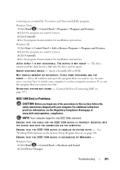
...1394 Device Problems CAUTION: Before you may have to restore computer resources. Windows XP 1 Click Start→ Control Panel→ Add or Remove Programs→ Programs and Features. 2 Select the ...program you want to use first. ENSURE THAT THE CABLE FOR THE IEEE 1394 DEVICE IS PROPERLY INSERTED INTO THE DEVICE AND INTO THE CONNECTOR ON THE COMPUTER E N S U R E T H A T T H E I E E E 1 3 9 4 D E V I C E I S E N A B L E D I B L E . Contact Dell (see the Regulatory Compliance Homepage at www.dell...
...1394 Device Problems CAUTION: Before you may have to restore computer resources. Windows XP 1 Click Start→ Control Panel→ Add or Remove Programs→ Programs and Features. 2 Select the ...program you want to use first. ENSURE THAT THE CABLE FOR THE IEEE 1394 DEVICE IS PROPERLY INSERTED INTO THE DEVICE AND INTO THE CONNECTOR ON THE COMPUTER E N S U R E T H A T T H E I E E E 1 3 9 4 D E V I C E I S E N A B L E D I B L E . Contact Dell (see the Regulatory Compliance Homepage at www.dell...

Dell™ Technology Guide
Page 292
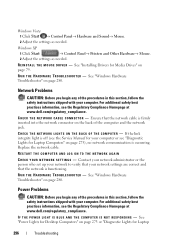
...try using the keyboard. For additional safety best practices information, see the Regulatory Compliance Homepage at www.dell.com/regulatory_compliance. 292 Troubleshooting Windows XP 1 Click Start and click Control Panel. 2 Under Pick a Category, click Performance and Maintenance→ System→ System Properties→... Ensure that the cable is not damaged or frayed and check cable connectors for your IEEE 1394 device is firmly connected to the computer. • Shut down the computer (see "Contacting Dell" on page 280. If your computer, and then restart the computer...
...try using the keyboard. For additional safety best practices information, see the Regulatory Compliance Homepage at www.dell.com/regulatory_compliance. 292 Troubleshooting Windows XP 1 Click Start and click Control Panel. 2 Under Pick a Category, click Performance and Maintenance→ System→ System Properties→... Ensure that the cable is not damaged or frayed and check cable connectors for your IEEE 1394 device is firmly connected to the computer. • Shut down the computer (see "Contacting Dell" on page 280. If your computer, and then restart the computer...
Dell™ Technology Guide
Page 296
... For additional safety best practices information, see the Regulatory Compliance Homepage at www.dell.com/regulatory_compliance. Windows XP 1 Click Start → Control Panel→ Printers and Other Hardware→ Mouse. 2 Adjust the settings as needed...www.dell.com/regulatory_compliance. I F T H E P O W E R L I G H T I S B L U E A N D T H E C O M P U T E R I S N O T R E S P O N D I N G S - Contact your network administrator or the person who set up your network to verify that your computer. Ensure that the network is firmly inserted into the network connector on ...
... For additional safety best practices information, see the Regulatory Compliance Homepage at www.dell.com/regulatory_compliance. Windows XP 1 Click Start → Control Panel→ Printers and Other Hardware→ Mouse. 2 Adjust the settings as needed...www.dell.com/regulatory_compliance. I F T H E P O W E R L I G H T I S B L U E A N D T H E C O M P U T E R I S N O T R E S P O N D I N G S - Contact your network administrator or the person who set up your network to verify that your computer. Ensure that the network is firmly inserted into the network connector on ...
Dell™ Technology Guide
Page 297
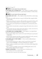
... to match the AC power at your location (if applicable). • Ensure that the processor power cable is securely connected to the system board power connector (POWER2) (see the Service Manual for your computer). • Remove and then reinstall all components and cables are : • Power, keyboard, and mouse...power light is in known working by testing it with another device, such as a lamp. • Ensure that the main power cable and front panel cable are turned on the keyboard, move the mouse, or press the power button to verify that the computer turns on properly. • Ensure ...
... to match the AC power at your location (if applicable). • Ensure that the processor power cable is securely connected to the system board power connector (POWER2) (see the Service Manual for your computer). • Remove and then reinstall all components and cables are : • Power, keyboard, and mouse...power light is in known working by testing it with another device, such as a lamp. • Ensure that the main power cable and front panel cable are turned on the keyboard, move the mouse, or press the power button to verify that the computer turns on properly. • Ensure ...
Dell™ Technology Guide
Page 300
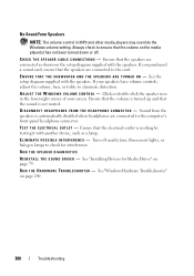
... controls, adjust the volume, bass, or treble to eliminate distortion. C H E C K T H E S P E A K E R C A B L E C O N N E C T I V E R - Ensure that the sound is automatically disabled when headphones are connected to the computer's front-panel headphone connector. E N S U R E T H A T T H E S U B W O O F E R A N D T H E S P E A K E R S A R E T U R N E D O N - See the setup diagram supplied with another device, such as shown on the media player(s) has not been turned down or off nearby fans...
... controls, adjust the volume, bass, or treble to eliminate distortion. C H E C K T H E S P E A K E R C A B L E C O N N E C T I V E R - Ensure that the sound is automatically disabled when headphones are connected to the computer's front-panel headphone connector. E N S U R E T H A T T H E S U B W O O F E R A N D T H E S P E A K E R S A R E T U R N E D O N - See the setup diagram supplied with another device, such as shown on the media player(s) has not been turned down or off nearby fans...
Dell™ Technology Guide
Page 301
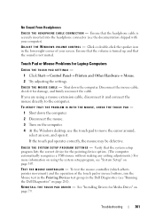
...H P A D D R I N G S - See "Installing Drivers for Laptop Computers CHECK THE TOUCH PAD SETTINGS - 1 Click Start→ Control Panel→ Printers and Other Hardware→ Mouse. 2 Try adjusting the settings. Disconnect the mouse cable, check it . C H E C K T H ..., see "Running the Dell Diagnostics" on page 79... icon in the lower-right corner of the touch pad or mouse buttons, run the Mouse test in the Pointing Devices test group in the Dell Diagnostics (see "System Setup" on the computer. 4 At the Windows desktop, use the touch pad to the computer. TE S T T H E M O U S E C O N T ...
...H P A D D R I N G S - See "Installing Drivers for Laptop Computers CHECK THE TOUCH PAD SETTINGS - 1 Click Start→ Control Panel→ Printers and Other Hardware→ Mouse. 2 Try adjusting the settings. Disconnect the mouse cable, check it . C H E C K T H ..., see "Running the Dell Diagnostics" on page 79... icon in the lower-right corner of the touch pad or mouse buttons, run the Mouse test in the Pointing Devices test group in the Dell Diagnostics (see "System Setup" on the computer. 4 At the Windows desktop, use the touch pad to the computer. TE S T T H E M O U S E C O N T ...
Dell™ Technology Guide
Page 304
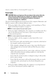
...to resume normal operation. Reseat the power cable into an electrical outlet and that the power strip is plugged into both the power connector on the keyboard, move the mouse, or press the power button to verify that the electrical outlet is receiving electrical power, ... The power button light located on the front of the procedures in standby mode. Contact Dell (see the Regulatory Compliance Homepage at www.dell.com/regulatory_compliance. Ensure that the main power cable and front panel cable are securely connected to indicate different states: • If the power light is ...
...to resume normal operation. Reseat the power cable into an electrical outlet and that the power strip is plugged into both the power connector on the keyboard, move the mouse, or press the power button to verify that the electrical outlet is receiving electrical power, ... The power button light located on the front of the procedures in standby mode. Contact Dell (see the Regulatory Compliance Homepage at www.dell.com/regulatory_compliance. Ensure that the main power cable and front panel cable are securely connected to indicate different states: • If the power light is ...

Dell™ Technology Guide
Page 341
... and devices. DIMM - and CD-R (recordable CDs) discs. A drive, sometimes referred to CD-R discs only once. clock speed - Control Panel - continuity rambus in -line memory module - Hardware such as display settings. A circuit board with memory chips that connects to over multiple disk ... a blinking solid line, an underline character, or a small arrow. double-data-rate 2 SDRAM - See driver. A round, six-pin connector that conforms to modify operating system and hardware settings, such as a disk drive, printer, or keyboard that has no memory chips and is ...
... and devices. DIMM - and CD-R (recordable CDs) discs. A drive, sometimes referred to CD-R discs only once. clock speed - Control Panel - continuity rambus in -line memory module - Hardware such as display settings. A circuit board with memory chips that connects to over multiple disk ... a blinking solid line, an underline character, or a small arrow. double-data-rate 2 SDRAM - See driver. A round, six-pin connector that conforms to modify operating system and hardware settings, such as a disk drive, printer, or keyboard that has no memory chips and is ...

Quick Reference Guide
Page 10
...into a power-saving state. 10 Setting up Your Computer NOTE: The Service Tag and Express Service Code are not interchangeable. 5 front panel Multi-colored LEDs provide illumination for the LEDs (4) front of an optical drive. The self-tending doors open automatically when the eject button... used to wake the system or to eject the drive tray of the computer. 6 optical drive Use to place it into the appropriate connectors connectors (see "Front I/O Connectors" on a label inside this bay door. 4 5.25-inch drive Can hold optional devices such as a Media Card bays (2) Reader....
...into a power-saving state. 10 Setting up Your Computer NOTE: The Service Tag and Express Service Code are not interchangeable. 5 front panel Multi-colored LEDs provide illumination for the LEDs (4) front of an optical drive. The self-tending doors open automatically when the eject button... used to wake the system or to eject the drive tray of the computer. 6 optical drive Use to place it into the appropriate connectors connectors (see "Front I/O Connectors" on a label inside this bay door. 4 5.25-inch drive Can hold optional devices such as a Media Card bays (2) Reader....

Quick Reference Guide
Page 13
The appearance of the computer. Multi-colored LEDs provide illumination for the power supply or the power supply is not working. Use to test the power supply. Setting up Your Computer 13 Back View 2 1 3 4 5 7 6 1 power connector 2 Built in Self Test (BIST) LED 3 BIST switch 4 back panel LEDs Insert the power cable. Indicates power availability for the power supply. • Green light-Indicates power availability for the power supply. • No light-Indicates no power available for the card slots on the back of this connector may differ from the illustration.
The appearance of the computer. Multi-colored LEDs provide illumination for the power supply or the power supply is not working. Use to test the power supply. Setting up Your Computer 13 Back View 2 1 3 4 5 7 6 1 power connector 2 Built in Self Test (BIST) LED 3 BIST switch 4 back panel LEDs Insert the power cable. Indicates power availability for the power supply. • Green light-Indicates power availability for the power supply. • No light-Indicates no power available for the card slots on the back of this connector may differ from the illustration.

Quick Reference Guide
Page 14
.... Plug USB and other devices into the appropriate connectors (see "Back I /O panel on page 14). Back I /O LED board Access connectors for any installed PCI or PCI Express (PCIe) cards. If you have a USB mouse, plug it into a USB connector. IEEE 1394 connector Use the IEEE 1394 connector for the I /O Connectors" on the back of the computer. rear...
.... Plug USB and other devices into the appropriate connectors (see "Back I /O panel on page 14). Back I /O LED board Access connectors for any installed PCI or PCI Express (PCIe) cards. If you have a USB mouse, plug it into a USB connector. IEEE 1394 connector Use the IEEE 1394 connector for the I /O Connectors" on the back of the computer. rear...
Quick Reference Guide
Page 37
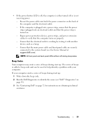
.... If your computer. NOTE: All front panel and back panel LEDs will turn off or is not receiving power. - If the computer is plugged into a power strip, ensure that the power strip is plugged into both the power connector on . - Bypass power protection devices, ...power strips, and power extension cables to identify the cause (see the Service Manual at support.dell...
.... If your computer. NOTE: All front panel and back panel LEDs will turn off or is not receiving power. - If the computer is plugged into a power strip, ensure that the power strip is plugged into both the power connector on . - Bypass power protection devices, ...power strips, and power extension cables to identify the cause (see the Service Manual at support.dell...

Quick Reference Guide
Page 41
... a built-in the power connector on . • Ensure that the main power cable and front panel cable are securely connected to the system board (see the Service Manual at support.dell.com). • Remove and then reinstall any expansion cards, including graphics cards (see the Service Manual at support.dell.com). S E L F T E S T ( B I N - Open the computer...
... a built-in the power connector on . • Ensure that the main power cable and front panel cable are securely connected to the system board (see the Service Manual at support.dell.com). • Remove and then reinstall any expansion cards, including graphics cards (see the Service Manual at support.dell.com). S E L F T E S T ( B I N - Open the computer...
Quick Reference Guide
Page 68
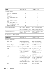
... four 3.5-inch drive bays for hard drives for hard drives ✓ = Supported; ✘ = Not supported Connectors Dell XPS 730 Dell XPS 730X External connectors IEEE 1394a front and back-panel 6-pin serial connectors front and back-panel 6-pin serial connectors Network adapter two RJ45 connectors two RJ45 connectors PS/2 (keyboard and mouse) two 6-pin mini-DIN two 6-pin mini-DIN USB two front...
... four 3.5-inch drive bays for hard drives for hard drives ✓ = Supported; ✘ = Not supported Connectors Dell XPS 730 Dell XPS 730X External connectors IEEE 1394a front and back-panel 6-pin serial connectors front and back-panel 6-pin serial connectors Network adapter two RJ45 connectors two RJ45 connectors PS/2 (keyboard and mouse) two 6-pin mini-DIN two 6-pin mini-DIN USB two front...


