Owner's Manual
Page 7
... 139 Removing the System Board 139 Installing the System Board 140 Power Supply 141 Power Supply (PSU) DC Connector Pin Assignments 142 Removing the Power Supply 151 Installing the Power Supply 154 Front I/O Panel 155 Front I/O-Panel Components 155 Removing the Front I/O Panel 156 Installing the I/O Panel 157 Battery 157 Replacing the Battery 157 Removing the Computer Stand 158...
... 139 Removing the System Board 139 Installing the System Board 140 Power Supply 141 Power Supply (PSU) DC Connector Pin Assignments 142 Removing the Power Supply 151 Installing the Power Supply 154 Front I/O Panel 155 Front I/O-Panel Components 155 Removing the Front I/O Panel 156 Installing the I/O Panel 157 Battery 157 Replacing the Battery 157 Removing the Computer Stand 158...
Owner's Manual
Page 141
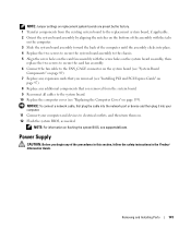
... components that you begin any of the procedures in this section, follow the safety instructions in the Product Information Guide. Power Supply CAUTION: Before you removed from the existing system board to the replacement system board, if applicable. 2 Orient the system board assembly by the factory. 1 Transfer components from the system board. 9 Reconnect... assembly clicks into your computer. 11 Connect your computer and devices to electrical outlets, and then turn them on flashing the system BIOS, see support.dell.com.
... components that you begin any of the procedures in this section, follow the safety instructions in the Product Information Guide. Power Supply CAUTION: Before you removed from the existing system board to the replacement system board, if applicable. 2 Orient the system board assembly by the factory. 1 Transfer components from the system board. 9 Reconnect... assembly clicks into your computer. 11 Connect your computer and devices to electrical outlets, and then turn them on flashing the system BIOS, see support.dell.com.
Owner's Manual
Page 151
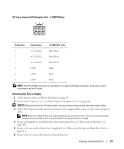
... the Optional Hard Drive Fan" on page 86). You must route these cables properly when you disconnect them from the power supply and disconnect each hard drive bay. DC Power Connector P16 (Graphics Card - 1-KW PSU Only) 456 123 Pin Number Signal Name 18-AWG Wire Color 1 +... cards whose power requirements exceed 75 watts. NOTICE: Note the location and ID of the power cable bundles as you replace them to prevent them . Removing and Installing Parts 151 NOTE: Note the routing of each power connector before disconnecting the power supply cables. 3 Follow the DC power cables that ...
... the Optional Hard Drive Fan" on page 86). You must route these cables properly when you disconnect them from the power supply and disconnect each hard drive bay. DC Power Connector P16 (Graphics Card - 1-KW PSU Only) 456 123 Pin Number Signal Name 18-AWG Wire Color 1 +... cards whose power requirements exceed 75 watts. NOTICE: Note the location and ID of the power cable bundles as you replace them to prevent them . Removing and Installing Parts 151 NOTE: Note the routing of each power connector before disconnecting the power supply cables. 3 Follow the DC power cables that ...
Owner's Manual
Page 154
...fan, if applicable (see "Replacing the Computer Cover" on . 154 Removing and Installing Parts NOTICE: To connect a network cable, first plug the cable into the network port or device and then plug it into place. 2 Replace the four screws that secure the power supply to electrical outlets, and ...then turn them . 7 Replace the computer cover (see "Installing the Optional Hard Drive Fan" on page 138). 6 Reattach each of...
...fan, if applicable (see "Replacing the Computer Cover" on . 154 Removing and Installing Parts NOTICE: To connect a network cable, first plug the cable into the network port or device and then plug it into place. 2 Replace the four screws that secure the power supply to electrical outlets, and ...then turn them . 7 Replace the computer cover (see "Installing the Optional Hard Drive Fan" on page 138). 6 Reattach each of...


