Owner's Manual
Page 93
... 141 for either the operating system or the program that was running when the message appeared. Troubleshooting Tools 93 Contact Dell (see "Contacting Dell" on page 141). Possible motherboard failure or RTC battery low. Replace the CPU fan (see the documentation for assistance). Code (repetitive short beeps) 5 6 7 Description Suggested Remedy RTC power failure.
... 141 for either the operating system or the program that was running when the message appeared. Troubleshooting Tools 93 Contact Dell (see "Contacting Dell" on page 141). Possible motherboard failure or RTC battery low. Replace the CPU fan (see the documentation for assistance). Code (repetitive short beeps) 5 6 7 Description Suggested Remedy RTC power failure.
Owner's Manual
Page 112
...The volume control in the Product Information Guide. RUN THE SPEAKER DIAGNOSTICS 112 Troubleshooting Windows XP: 1 Click Start→ Control Panel→ Printers and Other Hardware→ Scanners... as a lamp. See the setup diagram supplied with another device, such as shown on the media player(s) has not been turned down or off nearby fans, fluorescent lights, or halogen lamps to ensure that the electrical outlet is working by testing it with the speakers. D I N T E R F E R E N C E - E L I M I N A T E P O S S I B L E I S C O N N E C T H E A D P H O N E S F R O M T H...
...The volume control in the Product Information Guide. RUN THE SPEAKER DIAGNOSTICS 112 Troubleshooting Windows XP: 1 Click Start→ Control Panel→ Printers and Other Hardware→ Scanners... as a lamp. See the setup diagram supplied with another device, such as shown on the media player(s) has not been turned down or off nearby fans, fluorescent lights, or halogen lamps to ensure that the electrical outlet is working by testing it with the speakers. D I N T E R F E R E N C E - E L I M I N A T E P O S S I B L E I S C O N N E C T H E A D P H O N E S F R O M T H...
Owner's Manual
Page 114
... Panel→ Hardware and Sound→ Personalization→ Display Settings. 2 Adjust Resolution and Colors settings, as a lamp. M O V E T H E S U B W O O F E R A W A Y F R O M T H E M O N I C A L O U T L E T - Fans, fluorescent lights, halogen lamps, and other electrical devices can cause the screen image to change or click the Display icon. 3 Try different settings for Color...If the power light is off nearby devices to check for instructions on page 90. Windows XP: 1 Click Start→ Control Panel→ Appearance and Themes. 2 Click the area you want to appear shaky.
... Panel→ Hardware and Sound→ Personalization→ Display Settings. 2 Adjust Resolution and Colors settings, as a lamp. M O V E T H E S U B W O O F E R A W A Y F R O M T H E M O N I C A L O U T L E T - Fans, fluorescent lights, halogen lamps, and other electrical devices can cause the screen image to change or click the Display icon. 3 Try different settings for Color...If the power light is off nearby devices to check for instructions on page 90. Windows XP: 1 Click Start→ Control Panel→ Appearance and Themes. 2 Click the area you want to appear shaky.
Owner's Manual
Page 131
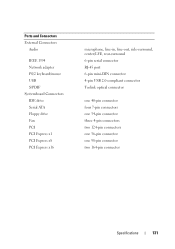
Ports and Connectors External Connectors Audio IEEE 1394 Network adapter PS/2 keyboard/mouse USB S/PDIF Systemboard Connectors IDE drive Serial ATA Floppy drive Fan PCI PCI Express x1 PCI Express x8 PCI Express x16 microphone, line-in, line-out, side-surround, center/LFE, rear-surround 6-pin serial connector RJ-...
Ports and Connectors External Connectors Audio IEEE 1394 Network adapter PS/2 keyboard/mouse USB S/PDIF Systemboard Connectors IDE drive Serial ATA Floppy drive Fan PCI PCI Express x1 PCI Express x8 PCI Express x16 microphone, line-in, line-out, side-surround, center/LFE, rear-surround 6-pin serial connector RJ-...
Service Manual
Page 5
Drive Panel 53 Removing the Drive Panel 53 Installing the Drive Panel 54 Floppy Drive 55 Removing a Floppy Drive 55 Installing a Floppy Drive 56 Media Card Reader 59 Removing a Media Card Reader 59 Installing a Media Card Reader 60 CD/DVD Drive 63 Removing a CD/DVD Drive 63 Installing a CD/DVD Drive 64 7 Fans 69 Removing the Card Fan 69 Installing the Card Fan 71 Removing the Hard Drive Fan 74 Installing the Hard Drive Fan 76 8 Processor Heatsink 79 Removing the Processor Heatsink 79 Installing the Processor Heatsink 80 Contents 5
Drive Panel 53 Removing the Drive Panel 53 Installing the Drive Panel 54 Floppy Drive 55 Removing a Floppy Drive 55 Installing a Floppy Drive 56 Media Card Reader 59 Removing a Media Card Reader 59 Installing a Media Card Reader 60 CD/DVD Drive 63 Removing a CD/DVD Drive 63 Installing a CD/DVD Drive 64 7 Fans 69 Removing the Card Fan 69 Installing the Card Fan 71 Removing the Hard Drive Fan 74 Installing the Hard Drive Fan 76 8 Processor Heatsink 79 Removing the Processor Heatsink 79 Installing the Processor Heatsink 80 Contents 5
Service Manual
Page 15
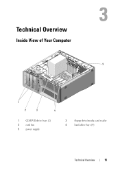
Technical Overview Inside View of Your Computer 5 1 2 3 4 1 CD/DVD drive bays (2) 3 card fan 5 power supply 2 floppy drive/media card reader 4 hard-drive bays (4) Technical Overview 15
Technical Overview Inside View of Your Computer 5 1 2 3 4 1 CD/DVD drive bays (2) 3 card fan 5 power supply 2 floppy drive/media card reader 4 hard-drive bays (4) Technical Overview 15
Service Manual
Page 17
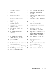
1 unused fan connector 2 power button (POWER_BTN) 3 front LED 4 front panel USB connector (FP_USB) 5 floppy drive (DSKT) 6 master I/O board USB connector (MIO_USB) 7 front panel IEEE connector (FP_1394) 8 reset ... slot is not available in the dual-graphics configuration 17 PCI-Express x16 card slot (PRIMARY_GFX_SLOT1) 18 power connector (12V_ATXP) 19 processor (CPU) 20 processor fan connector (FAN_CPU) 21 black memory module connectors 22 white memory module connectors (DIMM2 and DIMM 3) (DIMM0 and DIMM1) 23 main power connector (POWER) 24 IDE...
1 unused fan connector 2 power button (POWER_BTN) 3 front LED 4 front panel USB connector (FP_USB) 5 floppy drive (DSKT) 6 master I/O board USB connector (MIO_USB) 7 front panel IEEE connector (FP_1394) 8 reset ... slot is not available in the dual-graphics configuration 17 PCI-Express x16 card slot (PRIMARY_GFX_SLOT1) 18 power connector (12V_ATXP) 19 processor (CPU) 20 processor fan connector (FAN_CPU) 21 black memory module connectors 22 white memory module connectors (DIMM2 and DIMM 3) (DIMM0 and DIMM1) 23 main power connector (POWER) 24 IDE...
Service Manual
Page 32
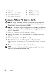
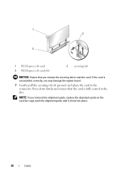
...). 3 Disconnect any cables connected to the card. 4 Press down the release tab on the alignment guide release tab to release the alignment guide from the fan cage. 32 Cards NOTE: If the card is full-length, pull back on the top of the card retainer at the appropriate card slot and...
...). 3 Disconnect any cables connected to the card. 4 Press down the release tab on the alignment guide release tab to release the alignment guide from the fan cage. 32 Cards NOTE: If the card is full-length, pull back on the top of the card retainer at the appropriate card slot and...
Service Manual
Page 33
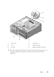
Cards 33 1 2 3 6 5 4 1 release tab 3 screw 5 fan cage 2 card retainer 4 alignment guide 6 alignment guide release tab 6 Press the securing tab (if present) on the system board connector as you grasp the card by its top corners, and then ease the card out of the connector.
Cards 33 1 2 3 6 5 4 1 release tab 3 screw 5 fan cage 2 card retainer 4 alignment guide 6 alignment guide release tab 6 Press the securing tab (if present) on the system board connector as you grasp the card by its top corners, and then ease the card out of the connector.
Service Manual
Page 34
... tab 7 Install a filler bracket in the empty card-slot opening. NOTE: If you are replacing the card, see "Replacing the Computer Cover" on the card fan cage; push the alignment guide until it clicks into place. 9 Push the card retainer back into the computer. 34 Cards If you removed the alignment...
... tab 7 Install a filler bracket in the empty card-slot opening. NOTE: If you are replacing the card, see "Replacing the Computer Cover" on the card fan cage; push the alignment guide until it clicks into place. 9 Push the card retainer back into the computer. 34 Cards If you removed the alignment...
Service Manual
Page 35
...Configuration" on page 40 to create a card-slot opening. 5 Prepare the card for your computer and devices to remove the alignment guide from the card fan cage. 6 Position the card so that you removed. Cards 35 NOTICE: If you have or are upgrading to the optional dual-graphics configuration, see "Installing... it is aligned with the slot and the securing tab (if present). NOTE: If the card is full-length, pull back on the card fan cage. NOTE: If the card is full-length, insert the card guide into the alignment slot on the alignment guide release tab to electrical outlets...
...Configuration" on page 40 to create a card-slot opening. 5 Prepare the card for your computer and devices to remove the alignment guide from the card fan cage. 6 Position the card so that you removed. Cards 35 NOTICE: If you have or are upgrading to the optional dual-graphics configuration, see "Installing... it is aligned with the slot and the securing tab (if present). NOTE: If the card is full-length, pull back on the card fan cage. NOTE: If the card is full-length, insert the card guide into the alignment slot on the alignment guide release tab to electrical outlets...
Service Manual
Page 36
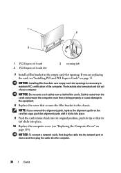
push the alignment guide until it clicks into place. 36 Cards If the card is fully seated in the connector. Press down firmly and ensure that you may damage the system board. 7 Gently pull the securing tab (if present) and place the card in the slot. 1 2 3 1 PCI Express x16 card 3 PCI Express x16 card slot 2 securing tab NOTICE: Ensure that the card is not installed correctly, you release the securing tab to seat the card. NOTE: If you removed the alignment guide, replace the alignment guide on the card fan cage;
push the alignment guide until it clicks into place. 36 Cards If the card is fully seated in the connector. Press down firmly and ensure that you may damage the system board. 7 Gently pull the securing tab (if present) and place the card in the slot. 1 2 3 1 PCI Express x16 card 3 PCI Express x16 card slot 2 securing tab NOTICE: Ensure that the card is not installed correctly, you release the securing tab to seat the card. NOTE: If you removed the alignment guide, replace the alignment guide on the card fan cage;
Service Manual
Page 58
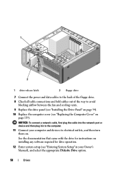
... cables to the back of the floppy drive. 8 Check all cable connections and fold cables out of the way to avoid blocking airflow between the fan and cooling vents. 9 Replace the drive panel (see "Installing the Drive Panel" on page 54). 10 Replace the computer cover (see "Entering System Setup" in...
... cables to the back of the floppy drive. 8 Check all cable connections and fold cables out of the way to avoid blocking airflow between the fan and cooling vents. 9 Replace the drive panel (see "Installing the Drive Panel" on page 54). 10 Replace the computer cover (see "Entering System Setup" in...
Service Manual
Page 62
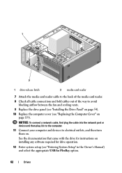
... the network port or device and then plug it in to the computer. 11 Connect your computer and devices to avoid blocking airflow between the fan and cooling vents. 9 Replace the drive panel (see "Installing the Drive Panel" on page 54). 10 Replace the computer cover (see "Replacing the Computer Cover...
... the network port or device and then plug it in to the computer. 11 Connect your computer and devices to avoid blocking airflow between the fan and cooling vents. 9 Replace the drive panel (see "Installing the Drive Panel" on page 54). 10 Replace the computer cover (see "Replacing the Computer Cover...
Service Manual
Page 67
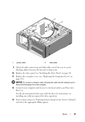
... the network port or device and then plug it in to the computer. 12 Connect your computer and devices to avoid blocking airflow between the fan and cooling vents. 10 Replace the drive panel (see "Installing the Drive Panel" on page 54). 11 Replace the computer cover (see "Entering System Setup...
... the network port or device and then plug it in to the computer. 12 Connect your computer and devices to avoid blocking airflow between the fan and cooling vents. 10 Replace the drive panel (see "Installing the Drive Panel" on page 54). 11 Replace the computer cover (see "Entering System Setup...
Service Manual
Page 69
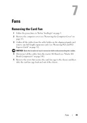
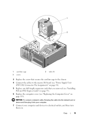
...: Note the location of the chassis. Fans Removing the Card Fan 1 Follow the procedures in "Before You Begin" on page 9. 2 Remove the computer cover (see "Removing the Computer Cover" on page 13). 3 Gather all the cables ... (see "Master I /O Board (see "Removing PCI and PCI Express Cards" on page 101). 5 Remove the screw that secures the card fan cage to the chassis and then slide the card fan cage back and out of each connector before disconnecting the cables. 4 Disconnect all the cables from the master I /O Board Components" on...
...: Note the location of the chassis. Fans Removing the Card Fan 1 Follow the procedures in "Before You Begin" on page 9. 2 Remove the computer cover (see "Removing the Computer Cover" on page 13). 3 Gather all the cables ... (see "Master I /O Board (see "Removing PCI and PCI Express Cards" on page 101). 5 Remove the screw that secures the card fan cage to the chassis and then slide the card fan cage back and out of each connector before disconnecting the cables. 4 Disconnect all the cables from the master I /O Board Components" on...
Service Manual
Page 70
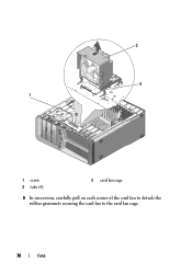
2 3 1 1 screw 3 tabs (4) 2 card fan cage 6 In succession, carefully pull on each corner of the card fan to detach the rubber grommets securing the card fan to the card fan cage. 70 Fans
2 3 1 1 screw 3 tabs (4) 2 card fan cage 6 In succession, carefully pull on each corner of the card fan to detach the rubber grommets securing the card fan to the card fan cage. 70 Fans
Service Manual
Page 71
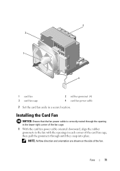
NOTE: Airflow direction and orientation are shown on the side of the fan. Installing the Card Fan NOTICE: Ensure that the fan power cable is correctly routed through the opening in the lower-right corner of the fan cage. 1 With the card fan power cable oriented downward, align the rubber grommets in the fan with the openings in a secure location. Fans 71 3 2 1 4 1 card fan 3 card fan cage 2 rubber grommet (4) 4 card fan power cable 7 Set the card fan aside in each corner of the card fan cage, then pull the grommets through until they snap into place.
NOTE: Airflow direction and orientation are shown on the side of the fan. Installing the Card Fan NOTICE: Ensure that the fan power cable is correctly routed through the opening in the lower-right corner of the fan cage. 1 With the card fan power cable oriented downward, align the rubber grommets in the fan with the openings in a secure location. Fans 71 3 2 1 4 1 card fan 3 card fan cage 2 rubber grommet (4) 4 card fan power cable 7 Set the card fan aside in each corner of the card fan cage, then pull the grommets through until they snap into place.
Service Manual
Page 72
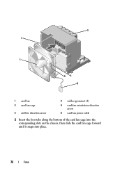
3 2 1 54 6 1 card fan 3 card fan cage 5 air-flow direction arrow 2 rubber grommet (4) 4 card-fan orientation direction arrow 6 card fan power cable 2 Insert the four tabs along the bottom of the card fan cage into the corresponding slots on the chassis, then slide the card fan cage forward until it snaps into place. 72 Fans
3 2 1 54 6 1 card fan 3 card fan cage 5 air-flow direction arrow 2 rubber grommet (4) 4 card-fan orientation direction arrow 6 card fan power cable 2 Insert the four tabs along the bottom of the card fan cage into the corresponding slots on the chassis, then slide the card fan cage forward until it snaps into place. 72 Fans
Service Manual
Page 73
... you removed (see "Installing PCI and PCI Express Cards" on page 35). 6 Replace the computer cover (see "Replacing the Computer Cover" on . 1 2 3 1 card fan cage 3 screw 2 tabs (4) 3 Replace the screw that secures the card fan cage to the chassis. 4 Connect the cables to electrical outlets, and then turn them on page 119...
... you removed (see "Installing PCI and PCI Express Cards" on page 35). 6 Replace the computer cover (see "Replacing the Computer Cover" on . 1 2 3 1 card fan cage 3 screw 2 tabs (4) 3 Replace the screw that secures the card fan cage to the chassis. 4 Connect the cables to electrical outlets, and then turn them on page 119...


