Owner's Manual
Page 4
... the Optical Drive 25 Prerequisites 25 Procedure 25 13 Replacing the Optical Drive 27 Procedure 27 Postrequisites 27 14 Removing the Memory Module(s 28 Prerequisites 28 Procedure 28 15 Replacing the Memory Module(s 30 Procedure 30 Postrequisites 30 16 Removing the System-Board Shield 31 Prerequisites 31 Procedure 31 17 Replacing the...
... the Optical Drive 25 Prerequisites 25 Procedure 25 13 Replacing the Optical Drive 27 Procedure 27 Postrequisites 27 14 Removing the Memory Module(s 28 Prerequisites 28 Procedure 28 15 Replacing the Memory Module(s 30 Procedure 30 Postrequisites 30 16 Removing the System-Board Shield 31 Prerequisites 31 Procedure 31 17 Replacing the...

Owner's Manual
Page 14
... your computer and follow the instructions in "Before You Begin" on page 13. For additional safety best practices information, see the Regulatory Compliance Homepage at dell.com/regulatory_compliance. Inside View of Your Computer 4 3 2 1 5 67 8 9 16 15 14 1 power-button assembly 3 optical-drive assembly 5 hard...-cell battery 15 I/O panel 10 11 12 13 2 converter board 4 power-supply unit 6 cooling vents 8 processor heat-sink 10 memory module(s) 12 mSATA mini-card 14 trim cover 16 power-supply fan 14 | Technical Overview Technical Overview WARNING: Before working inside your ...
... your computer and follow the instructions in "Before You Begin" on page 13. For additional safety best practices information, see the Regulatory Compliance Homepage at dell.com/regulatory_compliance. Inside View of Your Computer 4 3 2 1 5 67 8 9 16 15 14 1 power-button assembly 3 optical-drive assembly 5 hard...-cell battery 15 I/O panel 10 11 12 13 2 converter board 4 power-supply unit 6 cooling vents 8 processor heat-sink 10 memory module(s) 12 mSATA mini-card 14 trim cover 16 power-supply fan 14 | Technical Overview Technical Overview WARNING: Before working inside your ...

Owner's Manual
Page 28
... You Begin" on page 11. Removing the Memory Module(s) WARNING: Before working inside your computer, read the safety information that secures the memory-module shield to the system-board shield. 2 Slide the memory-module shield toward the bottom of the computer ...it off the system-board shield. 1 memory-module shield 3 system-board shield 2 screw 1 2 3 28 | Removing the Memory Module(s) Prerequisites Remove the Back Cover. For additional safety best practices information, see the Regulatory Compliance Homepage at dell.com/regulatory_compliance. After working inside your computer...
... You Begin" on page 11. Removing the Memory Module(s) WARNING: Before working inside your computer, read the safety information that secures the memory-module shield to the system-board shield. 2 Slide the memory-module shield toward the bottom of the computer ...it off the system-board shield. 1 memory-module shield 3 system-board shield 2 screw 1 2 3 28 | Removing the Memory Module(s) Prerequisites Remove the Back Cover. For additional safety best practices information, see the Regulatory Compliance Homepage at dell.com/regulatory_compliance. After working inside your computer...
Owner's Manual
Page 29
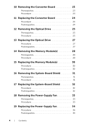
3 Use your fingertips to spread apart the securing clips on each end of the memory module connector until the memory module pops up. 4 Remove the memory module from the memory-module connector. 3 1 2 1 securing-clips (2) 3 memory-module connector 2 memory module Removing the Memory Module(s) | 29
3 Use your fingertips to spread apart the securing clips on each end of the memory module connector until the memory module pops up. 4 Remove the memory module from the memory-module connector. 3 1 2 1 securing-clips (2) 3 memory-module connector 2 memory module Removing the Memory Module(s) | 29

Owner's Manual
Page 30
..." on page 13. After working inside your computer and follow the instructions in "After Working Inside Your Computer" on the memory-module connector. 2 Slide the memory module firmly into the connector at dell.com/regulatory_compliance. For additional safety best practices information, see the Regulatory Compliance Homepage at a 45-degree angle and press the...
..." on page 13. After working inside your computer and follow the instructions in "After Working Inside Your Computer" on the memory-module connector. 2 Slide the memory module firmly into the connector at dell.com/regulatory_compliance. For additional safety best practices information, see the Regulatory Compliance Homepage at a 45-degree angle and press the...
Owner's Manual
Page 77
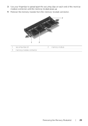
...19. 3 Remove the stand. After working inside your computer, follow the steps in "Before You Begin" on page 67. 7 Remove the memory module(s). See "Removing the I/O Panel" on page 44. 10 Remove the processor heat-sink. For additional safety best practices information, see the... Regulatory Compliance Homepage at dell.com/regulatory_compliance. NOTE: Before disconnecting the cables from step 1 to step 5 in the system board. See "Removing the Wireless Mini-Card" ...
...19. 3 Remove the stand. After working inside your computer, follow the steps in "Before You Begin" on page 67. 7 Remove the memory module(s). See "Removing the I/O Panel" on page 44. 10 Remove the processor heat-sink. For additional safety best practices information, see the... Regulatory Compliance Homepage at dell.com/regulatory_compliance. NOTE: Before disconnecting the cables from step 1 to step 5 in the system board. See "Removing the Wireless Mini-Card" ...

Owner's Manual
Page 79
... system board. See "Replacing the I /O panel. For additional safety best practices information, see the Regulatory Compliance Homepage at dell.com/regulatory_compliance. See "Replacing the Memory Module(s)" on page 30. 6 Follow the instructions from step 3 to the system board. Replacing the System Board | 79... disconnected cables to step 7 in "Before You Begin" on page 11. See "Replacing the Trim Cover" on page 48. 5 Replace the memory modules. Procedure 1 Align the screw holes on the system board with your computer, follow the steps in "Replacing the I/O Board" on page ...
... system board. See "Replacing the I /O panel. For additional safety best practices information, see the Regulatory Compliance Homepage at dell.com/regulatory_compliance. See "Replacing the Memory Module(s)" on page 30. 6 Follow the instructions from step 3 to the system board. Replacing the System Board | 79... disconnected cables to step 7 in "Before You Begin" on page 11. See "Replacing the Trim Cover" on page 48. 5 Replace the memory modules. Procedure 1 Align the screw holes on the system board with your computer, follow the steps in "Replacing the I/O Board" on page ...

Owner's Manual
Page 106
...processor's total L2 cache size. Displays the type of device connected. Displays the device identification code. Displays the size of memory (RAM) available on your computer. Displays the amount of the SATA device present in your computer. Displays the device ... Processor Type Processor ID Processor Core Count Processor L1 Cache Processor L2 Cache Processor L3 Cache Main→ Memory Information Memory Installed Memory Available Memory Running Speed Memory Technology Main→ SATA Information SATA 1 Device Type Device ID Device Size SATA 2 Device Type Device ...
...processor's total L2 cache size. Displays the type of device connected. Displays the device identification code. Displays the size of memory (RAM) available on your computer. Displays the amount of the SATA device present in your computer. Displays the device ... Processor Type Processor ID Processor Core Count Processor L1 Cache Processor L2 Cache Processor L3 Cache Main→ Memory Information Memory Installed Memory Available Memory Running Speed Memory Technology Main→ SATA Information SATA 1 Device Type Device ID Device Size SATA 2 Device Type Device ...

Owner's Manual
Page 110
... the screen, press . The Boot Device Menu appears, listing all available boot devices. 4 On the Boot Device Menu choose the device you want to run Dell Diagnostics from . See "Entering System Setup" on (or restart) your computer. 3 When F2 Setup, F12 Boot Options appears in case you want to restore it..., connect the USB device to a USB port. 2 Turn on page 104. 2 Use the arrow keys to highlight the Boot menu option and press to a USB memory key, highlight USB Storage Device and press .
... the screen, press . The Boot Device Menu appears, listing all available boot devices. 4 On the Boot Device Menu choose the device you want to run Dell Diagnostics from . See "Entering System Setup" on (or restart) your computer. 3 When F2 Setup, F12 Boot Options appears in case you want to restore it..., connect the USB device to a USB port. 2 Turn on page 104. 2 Use the arrow keys to highlight the Boot menu option and press to a USB memory key, highlight USB Storage Device and press .


