
Owners Manual
Page 46
... Information Guide. Ensure that the volume is turned up and that the volume on the media player(s) has not been turned down or off nearby fans, fluorescent lights, or halogen lamps to ensure that the sound is listed, Windows recognizes the scanner. Sound from speakers NOTE: The volume control in MP3...
... Information Guide. Ensure that the volume is turned up and that the volume on the media player(s) has not been turned down or off nearby fans, fluorescent lights, or halogen lamps to ensure that the sound is listed, Windows recognizes the scanner. Sound from speakers NOTE: The volume control in MP3...

Owners Manual
Page 48
... the monitor self-test. M O V E T H E S U B W O O F E R A W A Y F R O M T H E M O N I N G S - If your speaker system includes a subwoofer, ensure that the electrical outlet is at least 60 cm (2 ft) away from the monitor. Fans, fluorescent lights, halogen lamps, and other electrical devices can cause the screen image to check for instructions on page 49. Turn off nearby devices to...
... the monitor self-test. M O V E T H E S U B W O O F E R A W A Y F R O M T H E M O N I N G S - If your speaker system includes a subwoofer, ensure that the electrical outlet is at least 60 cm (2 ft) away from the monitor. Fans, fluorescent lights, halogen lamps, and other electrical devices can cause the screen image to check for instructions on page 49. Turn off nearby devices to...

Owners Manual
Page 64
CAUTION: To guard against electrical shock, always unplug your computer from the electrical outlet before opening the cover. 2 1 3 4 7 6 5 1 drive release latch 4 hard drive 7 front-panel door 2 CD/DVD drive 5 heat sink assembly 3 power supply and fan 6 power button 64 Removing and Installing Parts Inside View of Your Computer CAUTION: Before you begin any of the procedures in this section, follow the safety instructions located in the Product Information Guide.
CAUTION: To guard against electrical shock, always unplug your computer from the electrical outlet before opening the cover. 2 1 3 4 7 6 5 1 drive release latch 4 hard drive 7 front-panel door 2 CD/DVD drive 5 heat sink assembly 3 power supply and fan 6 power button 64 Removing and Installing Parts Inside View of Your Computer CAUTION: Before you begin any of the procedures in this section, follow the safety instructions located in the Product Information Guide.
Owners Manual
Page 66
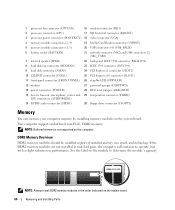
...board. If the DDR2 memory modules are not installed in matched pairs, the computer will continue to determine the module's capacity. 1 processor fan connector (CPUFAN) 16 modem connector (RJ11) 2 processor connector (CPU) 17 RJ11 internal connector (RJ11INT) 3 processor power connector (POWER12V...21 network connector (NIC) and USB connectors (2) (NIC_USB1) 7 internal speaker (SPKR) 22 back-panel IEEE 1394 connector (BACK1394) 8 hard disk fan connector (HDDFAN) 23 IEEE 1394 connector (INT1394) 9 hard disk connector (SATA0) 24 PCI Express x1 connector (SLOT2) 10 CD/DVD connector (...
...board. If the DDR2 memory modules are not installed in matched pairs, the computer will continue to determine the module's capacity. 1 processor fan connector (CPUFAN) 16 modem connector (RJ11) 2 processor connector (CPU) 17 RJ11 internal connector (RJ11INT) 3 processor power connector (POWER12V...21 network connector (NIC) and USB connectors (2) (NIC_USB1) 7 internal speaker (SPKR) 22 back-panel IEEE 1394 connector (BACK1394) 8 hard disk fan connector (HDDFAN) 23 IEEE 1394 connector (INT1394) 9 hard disk connector (SATA0) 24 PCI Express x1 connector (SLOT2) 10 CD/DVD connector (...

Owners Manual
Page 84
... into place. 2 1 1 CD/DVD drive 2 CD/DVD drive bracket 5 Check all cable connections, and fold cables out of the way to provide airflow for the fan and cooling vents. 6 Replace the computer cover (see "Replacing the Computer Cover" on page 96). 7 Connect your computer and devices to their electrical outlets, and.... 9 Enter system setup (see "System Setup" on page 101) and select the appropriate Drive option. 10 Verify that your computer works correctly by running the Dell Diagnostics (see "Dell Diagnostics" on page 52). 84 Removing and Installing Parts
... into place. 2 1 1 CD/DVD drive 2 CD/DVD drive bracket 5 Check all cable connections, and fold cables out of the way to provide airflow for the fan and cooling vents. 6 Replace the computer cover (see "Replacing the Computer Cover" on page 96). 7 Connect your computer and devices to their electrical outlets, and.... 9 Enter system setup (see "System Setup" on page 101) and select the appropriate Drive option. 10 Verify that your computer works correctly by running the Dell Diagnostics (see "Dell Diagnostics" on page 52). 84 Removing and Installing Parts

Owners Manual
Page 92
...that came with the drive for instructions on installing any software required for the fan and cooling vents. 5 Replace the CD/DVD drive (see "Installing a CD/DVD Drive" on page 83). 6 Replace the computer cover (see "Dell Diagnostics" on . NOTICE: To connect a network cable, first plug the ...cable in to the network device and then plug it in to the computer. 7 Connect your computer works correctly by running the Dell Diagnostics (see "Replacing the Computer Cover" on page 96). 3 Attach the interface cable to the system board (see "System Board Components" on page 65)....
...that came with the drive for instructions on installing any software required for the fan and cooling vents. 5 Replace the CD/DVD drive (see "Installing a CD/DVD Drive" on page 83). 6 Replace the computer cover (see "Dell Diagnostics" on . NOTICE: To connect a network cable, first plug the ...cable in to the network device and then plug it in to the computer. 7 Connect your computer works correctly by running the Dell Diagnostics (see "Replacing the Computer Cover" on page 96). 3 Attach the interface cable to the system board (see "System Board Components" on page 65)....
Owners Manual
Page 99
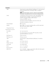
... to RJ11 one 2-pin connector two 7-pin connectors two 5-pin connectors (one for the CPU fan and one 2 x 5 header - Connectors USB Audio Network adapter Modem Temperature Sensor System board connectors: Serial ATA Fan PCI Express x1 PCI Express x16 USB MDC Floppy connector Front panel Power Processor power IEEE 1394...) one 12-pin connector one 26-pin connector one 40-pin header one 2 x 12 connector one 2 x 2 connector one for the optional hard disk fan connector.) 36-pin connector 164-pin connector 10-pin header for keying purposes. supports front-panel IEEE 1394 port Specifications 99
... to RJ11 one 2-pin connector two 7-pin connectors two 5-pin connectors (one for the CPU fan and one 2 x 5 header - Connectors USB Audio Network adapter Modem Temperature Sensor System board connectors: Serial ATA Fan PCI Express x1 PCI Express x16 USB MDC Floppy connector Front panel Power Processor power IEEE 1394...) one 12-pin connector one 26-pin connector one 40-pin header one 2 x 12 connector one 2 x 2 connector one for the optional hard disk fan connector.) 36-pin connector 164-pin connector 10-pin header for keying purposes. supports front-panel IEEE 1394 port Specifications 99


