
Owner's Manual
Page 5
... screen is blank 42 If the screen is difficult to read 43 3 Troubleshooting Tools Diagnostic Lights 45 Dell Diagnostics 48 When to Use the Dell Diagnostics 48 Dell Diagnostics Main Menu 48 Drivers 49 What Is a Driver 49 Reinstalling Drivers 50 Resolving Software and Hardware ...Incompatibilities 51 Restoring Your Operating System 51 Using Microsoft Windows XP System Restore 51 4 Removing and Installing Parts Before You Begin 55...
... screen is blank 42 If the screen is difficult to read 43 3 Troubleshooting Tools Diagnostic Lights 45 Dell Diagnostics 48 When to Use the Dell Diagnostics 48 Dell Diagnostics Main Menu 48 Drivers 49 What Is a Driver 49 Reinstalling Drivers 50 Resolving Software and Hardware ...Incompatibilities 51 Restoring Your Operating System 51 Using Microsoft Windows XP System Restore 51 4 Removing and Installing Parts Before You Begin 55...
Owner's Manual
Page 29
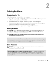
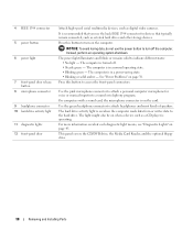
... N S U R E T H A T M I C R O S O F T ® W I N D O W S ® R E C O G N I Z E S T H E D R I V E - If the battery still does not work , ensure that the part is a danger of the procedures in this section, follow the safety instructions located in the Product Information Guide. Solving Problems 29 Discard used batteries according...message. Battery Problems CAUTION: There is correctly installed. • If a peripheral device does not work properly, contact Dell (see page 111). If you begin any of the procedures in this section, follow the safety instructions located in...
... N S U R E T H A T M I C R O S O F T ® W I N D O W S ® R E C O G N I Z E S T H E D R I V E - If the battery still does not work , ensure that the part is a danger of the procedures in this section, follow the safety instructions located in the Product Information Guide. Solving Problems 29 Discard used batteries according...message. Battery Problems CAUTION: There is correctly installed. • If a peripheral device does not work properly, contact Dell (see page 111). If you begin any of the procedures in this section, follow the safety instructions located in...

Owner's Manual
Page 48
... the possibility of tracing the problem quickly. Lists the most common symptoms encountered and allows you to 20 minutes and requires no interaction on your part. This test typically takes 10 to select a test based on page 29 and run (see page 55) and try again. 3 When the boot ... shut down the error code and problem description and follow the safety instructions located in the Product Information Guide. If you want to Use the Dell Diagnostics If you experience a problem with your computer, perform the checks in "Solving Problems" on the symptom of the problem you are having. 2 If ...
... the possibility of tracing the problem quickly. Lists the most common symptoms encountered and allows you to 20 minutes and requires no interaction on your part. This test typically takes 10 to select a test based on page 29 and run (see page 55) and try again. 3 When the boot ... shut down the error code and problem description and follow the safety instructions located in the Product Information Guide. If you want to Use the Dell Diagnostics If you experience a problem with your computer, perform the checks in "Solving Problems" on the symptom of the problem you are having. 2 If ...
Owner's Manual
Page 55
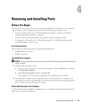
...shutdown process finishes. 2 Ensure that the following safety guidelines to help protect your computer from potential damage and to help ensure your Dell™ Product Information Guide. • A component can be replaced or-if purchased separately-installed by performing the removal procedure in ...Before Working Inside Your Computer" on page 55. • You have read the safety information in reverse order. Removing and Installing Parts 55 Unless otherwise noted, each procedure assumes that the computer and any open files, exit any attached devices are turned off your computer...
...shutdown process finishes. 2 Ensure that the following safety guidelines to help protect your computer from potential damage and to help ensure your Dell™ Product Information Guide. • A component can be replaced or-if purchased separately-installed by performing the removal procedure in ...Before Working Inside Your Computer" on page 55. • You have read the safety information in reverse order. Removing and Installing Parts 55 Unless otherwise noted, each procedure assumes that the computer and any open files, exit any attached devices are turned off your computer...
Owner's Manual
Page 56
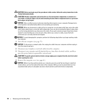
...pins. if you are correctly oriented and aligned. As you pull connectors apart, keep them evenly aligned to servicing that is not authorized by Dell is not covered by your computer (see page 61). Hold a component such as the metal at the back of the procedures in this... a cable, pull on its connector or on the locking tabs before you connect a cable, ensure that could harm internal components. 56 Removing and Installing Parts NOTICE: To avoid damaging the computer, perform the following steps before opening the cover. 4 Remove the computer cover (see page 55). NOTICE: To disconnect...
...pins. if you are correctly oriented and aligned. As you pull connectors apart, keep them evenly aligned to servicing that is not authorized by Dell is not covered by your computer (see page 61). Hold a component such as the metal at the back of the procedures in this... a cable, pull on its connector or on the locking tabs before you connect a cable, ensure that could harm internal components. 56 Removing and Installing Parts NOTICE: To avoid damaging the computer, perform the following steps before opening the cover. 4 Remove the computer cover (see page 55). NOTICE: To disconnect...

Owner's Manual
Page 57
... when the computer reads data from the drive. It is on booting to eject a CD/DVD from the CD or DVD drive. Removing and Installing Parts 57 The drive activity light is recommended that you use the back USB connectors for devices that typically remain connected, such as joysticks or cameras...
... when the computer reads data from the drive. It is on booting to eject a CD/DVD from the CD or DVD drive. Removing and Installing Parts 57 The drive activity light is recommended that you use the back USB connectors for devices that typically remain connected, such as joysticks or cameras...
Owner's Manual
Page 58
... also be on page 38. This panel covers the CD/DVD drive, the Media Card Reader, and the optional floppy drive. 58 Removing and Installing Parts
... also be on page 38. This panel covers the CD/DVD drive, the Media Card Reader, and the optional floppy drive. 58 Removing and Installing Parts

Owner's Manual
Page 59
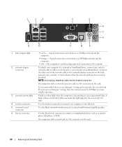
Removing and Installing Parts 59 Back View 1 2 3 4 1 voltage selection switch (may not be available See the safety instructions in the Product on all computers) Information Guide for more information. 2 power connector Insert the power cable. 3 back panel connectors Plug IEEE 1394, USB and other devices into the appropriate connector. 4 card slots Access connectors for any installed PCI Express cards.
Removing and Installing Parts 59 Back View 1 2 3 4 1 voltage selection switch (may not be available See the safety instructions in the Product on all computers) Information Guide for more information. 2 power connector Insert the power cable. 3 back panel connectors Plug IEEE 1394, USB and other devices into the appropriate connector. 4 card slots Access connectors for any installed PCI Express cards.
Owner's Manual
Page 60
... traffic may make this light appear to connect your network. Use the modem connector to be in a steady "on the card. 60 Removing and Installing Parts On computers with a network connector card, use the connector on " state. A good connection exists between a 100-Mbps network and the computer. • Off - A good connection...
... traffic may make this light appear to connect your network. Use the modem connector to be in a steady "on the card. 60 Removing and Installing Parts On computers with a network connector card, use the connector on " state. A good connection exists between a 100-Mbps network and the computer. • Off - A good connection...

Owner's Manual
Page 61
... of 80 Hz and below. Removing the Computer Cover CAUTION: Before you shut down the computer through an analog audio conversion process. Removing and Installing Parts 61 If your computer and all attached devices from the electrical outlet before opening the cover. This connector is recommended that you connect occasionally, such...
... of 80 Hz and below. Removing the Computer Cover CAUTION: Before you shut down the computer through an analog audio conversion process. Removing and Installing Parts 61 If your computer and all attached devices from the electrical outlet before opening the cover. This connector is recommended that you connect occasionally, such...

Owner's Manual
Page 62
... , using the bottom hinges as leverage points. 9 Release the cover from the hinge tabs and set it aside in a secure location. 62 Removing and Installing Parts NOTICE: Ensure that you are working on a level, protected surface to avoid scratching either the computer or the surface on which it is resting. 5 Lay...
... , using the bottom hinges as leverage points. 9 Release the cover from the hinge tabs and set it aside in a secure location. 62 Removing and Installing Parts NOTICE: Ensure that you are working on a level, protected surface to avoid scratching either the computer or the surface on which it is resting. 5 Lay...
Owner's Manual
Page 63
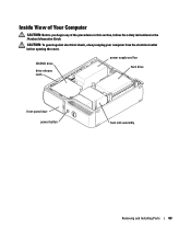
CAUTION: To guard against electrical shock, always unplug your computer from the electrical outlet before opening the cover. Inside View of Your Computer CAUTION: Before you begin any of the procedures in this section, follow the safety instructions in the Product Information Guide. CD/DVD drive drive release latch power supply and fan hard drive front-panel door power button heat sink assembly Removing and Installing Parts 63
CAUTION: To guard against electrical shock, always unplug your computer from the electrical outlet before opening the cover. Inside View of Your Computer CAUTION: Before you begin any of the procedures in this section, follow the safety instructions in the Product Information Guide. CD/DVD drive drive release latch power supply and fan hard drive front-panel door power button heat sink assembly Removing and Installing Parts 63
Owner's Manual
Page 64
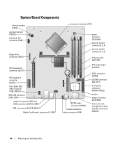
... connector (IDE_OPT) front-panel connector (FRONT PANEL) modem power connector (ATXPWR1) line-in, line-out, microphone, center, and LFE connectors (AUDIO) 64 Removing and Installing Parts
... connector (IDE_OPT) front-panel connector (FRONT PANEL) modem power connector (ATXPWR1) line-in, line-out, microphone, center, and LFE connectors (AUDIO) 64 Removing and Installing Parts
Owner's Manual
Page 65
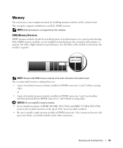
... slowest module installed. • Be sure to install a single memory module in DIMM connector 1, the connector closest to determine the module's capacity. Removing and Installing Parts 65 DDR2 Memory Overview DDR2 memory modules should be installed in the order indicated on the module to the processor, before you install modules in...
... slowest module installed. • Be sure to install a single memory module in DIMM connector 1, the connector closest to determine the module's capacity. Removing and Installing Parts 65 DDR2 Memory Overview DDR2 memory modules should be installed in the order indicated on the module to the processor, before you install modules in...

Owner's Manual
Page 66
...or optional floppy drive, (see page 82 or page 85) if installed. 66 Removing and Installing Parts You can use a maximum of 4 GB of address space; If possible, do so by computer...memory when you use two 2-GB DIMMs. Current operating systems, such as Microsoft® Windows® XP, can do not pair an original memory module with a new memory module. matched pair of memory ... instructions located in the Product Information Guide. Otherwise, your computer, discharge static electricity from Dell is less than 4 GB. NOTICE: If you may not start properly. Installing Memory CAUTION...
...or optional floppy drive, (see page 82 or page 85) if installed. 66 Removing and Installing Parts You can use a maximum of 4 GB of address space; If possible, do so by computer...memory when you use two 2-GB DIMMs. Current operating systems, such as Microsoft® Windows® XP, can do not pair an original memory module with a new memory module. matched pair of memory ... instructions located in the Product Information Guide. Otherwise, your computer, discharge static electricity from Dell is less than 4 GB. NOTICE: If you may not start properly. Installing Memory CAUTION...
Owner's Manual
Page 67
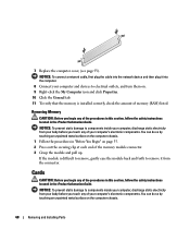
... the module correctly, the securing clips snap into the cutouts at each end of the module with the crossbar in the connector. Removing and Installing Parts 67 4 Press out the securing clip at each end of the module. 6 Insert the module into the connector until the module snaps into the connector...
... the module correctly, the securing clips snap into the cutouts at each end of the module with the crossbar in the connector. Removing and Installing Parts 67 4 Press out the securing clip at each end of the module. 6 Insert the module into the connector until the module snaps into the connector...
Owner's Manual
Page 68
... located in the Product Information Guide. NOTICE: To prevent static damage to electrical outlets, and turn them on the computer chassis. 68 Removing and Installing Parts NOTICE: To connect a network cable, first plug the cable into the network device and then plug it from the connector. Removing Memory CAUTION: Before you...
... located in the Product Information Guide. NOTICE: To prevent static damage to electrical outlets, and turn them on the computer chassis. 68 Removing and Installing Parts NOTICE: To connect a network cable, first plug the cable into the network device and then plug it from the connector. Removing Memory CAUTION: Before you...
Owner's Manual
Page 69
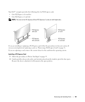
Removing and Installing Parts 69 Your Dell™ computer provides the following slots for PCI Express cards: • One PCI Express x16 card slot • One PCI Express x1 card slot NOTE: ...
Removing and Installing Parts 69 Your Dell™ computer provides the following slots for PCI Express cards: • One PCI Express x16 card slot • One PCI Express x1 card slot NOTE: ...

Owner's Manual
Page 70
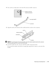
... installing any cables connected to unplug your computer. Ensure that came with the securing tab, and gently pull the securing tab. 70 Removing and Installing Parts If necessary, disconnect any cards. 6 Place the card in the connector and press down firmly. retention arm tab PCI Express card edge connector securing slot...
... installing any cables connected to unplug your computer. Ensure that came with the securing tab, and gently pull the securing tab. 70 Removing and Installing Parts If necessary, disconnect any cards. 6 Place the card in the connector and press down firmly. retention arm tab PCI Express card edge connector securing slot...

Owner's Manual
Page 71
Removing and Installing Parts 71 Ensure that : • The tops of all cards and filler brackets are flush with the alignment bar. • The notch in the top of the card or filler bracket fits around the alignment guide. 8 Place the card in the slot. card not fully seated card fully seated bracket within slot bracket caught outside of slot 9 Before you close the card retention door, ensure that the card is fully seated in the connector and press down firmly.
Removing and Installing Parts 71 Ensure that : • The tops of all cards and filler brackets are flush with the alignment bar. • The notch in the top of the card or filler bracket fits around the alignment guide. 8 Place the card in the slot. card not fully seated card fully seated bracket within slot bracket caught outside of slot 9 Before you close the card retention door, ensure that the card is fully seated in the connector and press down firmly.

