
Service Manual
Page 4
... Removing the power button and optional fingerprint reader 44 Installing the power button with optional fingerprint reader 45 DC-in port...47 Removing the DC-in port...47 Installing the DC-in port...48 Touchpad...49 Removing the touchpad...49 Installing the touchpad...50 Display assembly...51 Removing the display assembly...51 Installing...
... Removing the power button and optional fingerprint reader 44 Installing the power button with optional fingerprint reader 45 DC-in port...47 Removing the DC-in port...47 Installing the DC-in port...48 Touchpad...49 Removing the touchpad...49 Installing the touchpad...50 Display assembly...51 Removing the display assembly...51 Installing...

Service Manual
Page 10
DC-in port 7. Speaker 8. Touchpad 10. Display assembly 12. Power button with fingerprint reader 13. WLAN card 17. Base cover 2. Coin-cell battery 14. Heat sink 5. I/O board 15. Palm-rest and keyboard assembly 11. GPU fan 16. Memory module 6. M.2 2280 SSD 10 Major components of your system 2 Major components of your system 1. Battery 3. System board 9. System fan 4.
DC-in port 7. Speaker 8. Touchpad 10. Display assembly 12. Power button with fingerprint reader 13. WLAN card 17. Base cover 2. Coin-cell battery 14. Heat sink 5. I/O board 15. Palm-rest and keyboard assembly 11. GPU fan 16. Memory module 6. M.2 2280 SSD 10 Major components of your system 2 Major components of your system 1. Battery 3. System board 9. System fan 4.

Service Manual
Page 13
Disassembly and reassembly 13 About this task The figure indicates the location of the base cover and provides a visual representation of the removal procedure. Component Hinge screws Screw type M2.5x5 M2.5x4 Quantity 2 2 Screw image I/O board M2x3 1 Power button with fingerprint M1.6x2.5 2 reader DC-in port M2x3 1 Touchpad M2x2 3 M1.6x2 2 Display assembly M2.5x5 2 M2.5x4 2 System board M2x3 4 Base cover Removing the base cover Prerequisites Follow the procedure in before working inside your computer.
Disassembly and reassembly 13 About this task The figure indicates the location of the base cover and provides a visual representation of the removal procedure. Component Hinge screws Screw type M2.5x5 M2.5x4 Quantity 2 2 Screw image I/O board M2x3 1 Power button with fingerprint M1.6x2.5 2 reader DC-in port M2x3 1 Touchpad M2x2 3 M1.6x2 2 Display assembly M2.5x5 2 M2.5x4 2 System board M2x3 4 Base cover Removing the base cover Prerequisites Follow the procedure in before working inside your computer.

Service Manual
Page 47
Follow the procedure in port and provides a visual representation of the removal procedure. Remove the battery. About this task The figure indicates the location of 90 degrees. 3. Remove the two screws (M2.5x5) and (M2.5x4) that secures the DC-in port Prerequisites 1. Remove the base cover. 3. ...Disassembly and reassembly 47 DC-in port Removing the DC-in port to the palm-rest and keyboard assembly. 2. Open the left display hinge to the palm-rest...
Follow the procedure in port and provides a visual representation of the removal procedure. Remove the battery. About this task The figure indicates the location of 90 degrees. 3. Remove the two screws (M2.5x5) and (M2.5x4) that secures the DC-in port Prerequisites 1. Remove the base cover. 3. ...Disassembly and reassembly 47 DC-in port Removing the DC-in port to the palm-rest and keyboard assembly. 2. Open the left display hinge to the palm-rest...

Service Manual
Page 48
... the system board. 4. About this task The figure indicates the location of the DC-in port, along with its cable, off the palm-rest and keyboard assembly. Replace the single screw (M2x3) that secure the left display hinge. 5. Using the alignment... posts, close the left display hinge to the system board. 48 Disassembly and reassembly Installing the DC-in port on the palm-rest and keyboard assembly. 2. Place the DC-in port Prerequisites If you are replacing a component, remove the existing component before performing the installation procedure. Replace the two screws...
... the system board. 4. About this task The figure indicates the location of the DC-in port, along with its cable, off the palm-rest and keyboard assembly. Replace the single screw (M2x3) that secure the left display hinge. 5. Using the alignment... posts, close the left display hinge to the system board. 48 Disassembly and reassembly Installing the DC-in port on the palm-rest and keyboard assembly. 2. Place the DC-in port Prerequisites If you are replacing a component, remove the existing component before performing the installation procedure. Replace the two screws...

Service Manual
Page 57
...palm-rest and keyboard assembly. 12. Disconnect the speaker cable from the system board. 8. Remove the two screws (M2x3) that secure the USB Type-C port bracket to the system board. 10. Open the latch, and disconnect the touchpad cable from the system board. 7. Remove the two screws (M2x3) that...keyboard-backlight cable from the slots on the palm-rest and keyboard assembly and lift the system board off the system board. 5. Gently release the ports on the system board from the system board. 9. Disassembly and reassembly 57 Remove two screws (M2.5x5) and (M2.5x4), and lift the...
...palm-rest and keyboard assembly. 12. Disconnect the speaker cable from the system board. 8. Remove the two screws (M2x3) that secure the USB Type-C port bracket to the system board. 10. Open the latch, and disconnect the touchpad cable from the system board. 7. Remove the two screws (M2x3) that...keyboard-backlight cable from the slots on the palm-rest and keyboard assembly and lift the system board off the system board. 5. Gently release the ports on the system board from the system board. 9. Disassembly and reassembly 57 Remove two screws (M2.5x5) and (M2.5x4), and lift the...

Service Manual
Page 59
Replace the two screws (M2x3) that secure the USB Type-C port bracket to secure the cable. 8. Install the SSD-1 (M.2 2280 or M.2 2230). 7. Install the .... 2. Install the GPU fan. 4. Install the system fan. 5. Align and place the USB Type-C port bracket. 4. Adhere the tape that secure the system board to secure the cable. 6. Install the battery. 9. Steps 1. Slide the... ports on the system board into the slots on the palm-rest and keyboard assembly and align the screw ...
Replace the two screws (M2x3) that secure the USB Type-C port bracket to secure the cable. 8. Install the SSD-1 (M.2 2280 or M.2 2230). 7. Install the .... 2. Install the GPU fan. 4. Install the system fan. 5. Align and place the USB Type-C port bracket. 4. Adhere the tape that secure the system board to secure the cable. 6. Install the battery. 9. Steps 1. Slide the... ports on the system board into the slots on the palm-rest and keyboard assembly and align the screw ...

Service Manual
Page 60
... assembly. Remove the heat sink - Steps After performing the steps in the pre-requisites, you are left with fingerprint reader. 14. Follow the procedure in port. 13. Remove the battery. 4. Remove the GPU fan. 8. Palm-rest and keyboard assembly Removing the palm-rest and keyboard assembly Prerequisites 1. Remove the memory module...
... assembly. Remove the heat sink - Steps After performing the steps in the pre-requisites, you are left with fingerprint reader. 14. Follow the procedure in port. 13. Remove the battery. 4. Remove the GPU fan. 8. Palm-rest and keyboard assembly Removing the palm-rest and keyboard assembly Prerequisites 1. Remove the memory module...

Service Manual
Page 61
.... 11. Next steps 1. Install the DC-in after working inside your computer. Install the memory module. 9. Install the GPU fan. 12. Follow the procedure in port. 4. Installing the palm-rest and keyboard assembly Prerequisites If you are replacing a component, remove the existing component before performing the installation procedure. Install the display...
.... 11. Next steps 1. Install the DC-in after working inside your computer. Install the memory module. 9. Install the GPU fan. 12. Follow the procedure in port. 4. Installing the palm-rest and keyboard assembly Prerequisites If you are replacing a component, remove the existing component before performing the installation procedure. Install the display...
Service Manual
Page 66
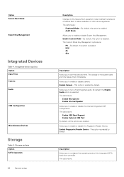
... driver signatures. Allows you to enable or disable camera. The Custom Mode Key Management options are : • Enable USB Boot Support • Enable External USB Port By default, all integrated audio. The change to enable or disable the Fingerprint Reader Device. Allows you to turn off all the options are : •...
... driver signatures. Allows you to enable or disable camera. The Custom Mode Key Management options are : • Enable USB Boot Support • Enable External USB Port By default, all integrated audio. The change to enable or disable the Fingerprint Reader Device. Allows you to turn off all the options are : •...
Service Manual
Page 69
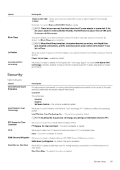
... power on Next Boot Allows BIOS to queue up data wipe cycle for Clear Command - This option enables you to connect a Dell USB-C Dock to wake the system from all USB ports to select appropriate processor performance. NOTE: These features are : • Disabled • Enabled • Software Control-This option is enabled... Allows you to clear the PTT owner information and return PTT to sleep. Option Block Sleep Lid Switch Intel Speed Shift technology Description Wake on Dell USB-C Dock is enabled. By default, the option Wake on...
... power on Next Boot Allows BIOS to queue up data wipe cycle for Clear Command - This option enables you to connect a Dell USB-C Dock to wake the system from all USB ports to select appropriate processor performance. NOTE: These features are : • Disabled • Enabled • Software Control-This option is enabled... Allows you to clear the PTT owner information and return PTT to sleep. Option Block Sleep Lid Switch Intel Speed Shift technology Description Wake on Dell USB-C Dock is enabled. By default, the option Wake on...

Service Manual
Page 77
... Flash from file. From a power off state, insert the USB key where you downloaded from the Dell Support website and copied to see if BIOS UPDATE is listed as a boot option for your system. Most Dell systems built after 2012 have to be bootable). • BIOS executable file that you copied the... flash into a USB port of the USB key. • AC power adapter that is copied to access the One...
... Flash from file. From a power off state, insert the USB key where you downloaded from the Dell Support website and copied to see if BIOS UPDATE is listed as a boot option for your system. Most Dell systems built after 2012 have to be bootable). • BIOS executable file that you copied the... flash into a USB port of the USB key. • AC power adapter that is copied to access the One...

Setup and specifications guide
Page 3
... view...8 Palm-rest view...9 Bottom view...10 Keyboard shortcuts...10 Chapter 3: System specifications...12 Processors...12 Chipset...13 Operating system...13 Memory...13 Storage...13 Ports and connectors...14 Audio...14 Video...15 Camera...15 Communications...16 Media-card reader...16 Power adapter...16 Battery...17 Dimensions and weight...17 Display...
... view...8 Palm-rest view...9 Bottom view...10 Keyboard shortcuts...10 Chapter 3: System specifications...12 Processors...12 Chipset...13 Operating system...13 Memory...13 Storage...13 Ports and connectors...14 Audio...14 Video...15 Camera...15 Communications...16 Media-card reader...16 Power adapter...16 Battery...17 Dimensions and weight...17 Display...

Setup and specifications guide
Page 8
HDMI 2.0 port 4. microSD card reader 2. USB 3.2 Gen 2 Type-C port with Thunderbolt 3/DisplayPort alt mode (optional) Right view 1. USB 3.2 Gen 1 Type-A port 3. Power connector port 2. Power LED 3. USB 3.2 Gen 1 Type-A port 5. Left view 1. Universal audio jack 8 Chassis overview
HDMI 2.0 port 4. microSD card reader 2. USB 3.2 Gen 2 Type-C port with Thunderbolt 3/DisplayPort alt mode (optional) Right view 1. USB 3.2 Gen 1 Type-A port 3. Power connector port 2. Power LED 3. USB 3.2 Gen 1 Type-A port 5. Left view 1. Universal audio jack 8 Chassis overview

Setup and specifications guide
Page 12
... with your computer. The following specifications are only those required by region. Topics: • Processors • Chipset • Operating system • Memory • Storage • Ports and connectors • Audio • Video • Camera • Communications • Media-card reader • Power adapter • Battery • Dimensions and weight • Display...
... with your computer. The following specifications are only those required by region. Topics: • Processors • Chipset • Operating system • Memory • Storage • Ports and connectors • Audio • Video • Camera • Communications • Media-card reader • Power adapter • Battery • Dimensions and weight • Display...

Setup and specifications guide
Page 14
... 3x4 PCIe NVMe 3x4 PCIe NVMe 3x4 Capacity Up to 512 GB Up to 2 TB Up to 512 GB Ports and connectors Table 7. Audio specifications Description Controller Stereo conversion Internal interface External interface Speakers Values Realtek ALC3204 Supported High ...Universal Audio Jack 2 14 System specifications Audio Table 9. Internal ports and connectors Internal: M.2 • 2 USB 3.2 Gen 1 Type-A ports • 1 USB 3.2 Gen 1 Type-C port with DisplayPort alt mode/Power Delivery (optional) • 1 USB 3.2 Gen 2 port with Thunderbolt/DisplayPort alt mode/ Power Delivery (optional) One...
... 3x4 PCIe NVMe 3x4 PCIe NVMe 3x4 Capacity Up to 512 GB Up to 2 TB Up to 512 GB Ports and connectors Table 7. Audio specifications Description Controller Stereo conversion Internal interface External interface Speakers Values Realtek ALC3204 Supported High ...Universal Audio Jack 2 14 System specifications Audio Table 9. Internal ports and connectors Internal: M.2 • 2 USB 3.2 Gen 1 Type-A ports • 1 USB 3.2 Gen 1 Type-C port with DisplayPort alt mode/Power Delivery (optional) • 1 USB 3.2 Gen 2 port with Thunderbolt/DisplayPort alt mode/ Power Delivery (optional) One...

Setup and specifications guide
Page 15
... controls 2 W 2.5 W Not supported Dual-array microphones Video Table 10. Integrated graphics specifications Integrated graphics Controller External display support Intel UHD Graphics DisplayPort over USB Type-C port Memory size 4 GB 4 GB Memory Type GDDR6 GDDR6 Memory size Shared system memory Processor 10th Generation Intel Core i5/i7 Camera Table 12.
... controls 2 W 2.5 W Not supported Dual-array microphones Video Table 10. Integrated graphics specifications Integrated graphics Controller External display support Intel UHD Graphics DisplayPort over USB Type-C port Memory size 4 GB 4 GB Memory Type GDDR6 GDDR6 Memory size Shared system memory Processor 10th Generation Intel Core i5/i7 Camera Table 12.

Setup and specifications guide
Page 25
This option is disabled. The options are: • Enable USB Boot Support • Enable External USB Port By default, all integrated audio. Enable Fingerprint Reader Device - System setup 25 Enable Custom Mode-By default, this option is enabled by default. The change ...
This option is disabled. The options are: • Enable USB Boot Support • Enable External USB Port By default, all integrated audio. Enable Fingerprint Reader Device - System setup 25 Enable Custom Mode-By default, this option is enabled by default. The change ...

Setup and specifications guide
Page 28
... you to block entering to control the Trusted Platform Module (TPM). By default, the option Wake on Dell USB-C Dock is enabled by system battery) from all USB ports to sleep. By default, the Block Sleep option is enabled. Lid Switch Allows the system to select ...default,Intel Speed Shift technology is disabled. Allows you to the operating system. NOTE: Disabling this option allows the operating system to power on Dell USB- Power Management (continued) Option Description • Cool • Quiet • Ultra Performance USB Wake Support Enable USB Wake Allows you...
... you to block entering to control the Trusted Platform Module (TPM). By default, the option Wake on Dell USB-C Dock is enabled by system battery) from all USB ports to sleep. By default, the Block Sleep option is enabled. Lid Switch Allows the system to select ...default,Intel Speed Shift technology is disabled. Allows you to the operating system. NOTE: Disabling this option allows the operating system to power on Dell USB- Power Management (continued) Option Description • Cool • Quiet • Ultra Performance USB Wake Support Enable USB Wake Allows you...

Setup and specifications guide
Page 36
... recovery key to flash the BIOS. If the option is listed as Ubuntu, see https://www.dell.com/support/article/sln171755/. NOTE: Only systems with BitLocker enabled CAUTION: If BitLocker is copied to... system battery to progress and the system will not recognize the BitLocker key. Updating from the Dell Support website and copied to access the One-Time Boot Menu. 3. Flashing the BIOS from the... setup From a power off state, insert the USB key where you copied the flash into a USB port of the USB key. • AC power adapter that you need: • USB key formatted to...
... recovery key to flash the BIOS. If the option is listed as Ubuntu, see https://www.dell.com/support/article/sln171755/. NOTE: Only systems with BitLocker enabled CAUTION: If BitLocker is copied to... system battery to progress and the system will not recognize the BitLocker key. Updating from the Dell Support website and copied to access the One-Time Boot Menu. 3. Flashing the BIOS from the... setup From a power off state, insert the USB key where you copied the flash into a USB port of the USB key. • AC power adapter that you need: • USB key formatted to...


