
Setup and Specifications
Page 3
... a USB recovery drive for Windows 6 3 Chassis overview...7 Display...7 Right...7 Left...8 Base...8 Bottom...9 4 Specifications of Vostro 5590...10 Chipset...10 Processors...10 Operating system...10 Memory...10 Ports and connectors...11 Communications...12 Audio...12 Storage...13 Intel Optane memory (optional)...13 Media-card reader...14 Keyboard...14 Camera...14 Touchpad...15 Touchpad ......15 Power adapter...15 Battery...15 Dimensions and weight...16 Display...16 Fingerprint reader (optional)...17 Video...17 Computer environment...18 5 Getting help...19 Contacting Dell...19 Contents 3
... a USB recovery drive for Windows 6 3 Chassis overview...7 Display...7 Right...7 Left...8 Base...8 Bottom...9 4 Specifications of Vostro 5590...10 Chipset...10 Processors...10 Operating system...10 Memory...10 Ports and connectors...11 Communications...12 Audio...12 Storage...13 Intel Optane memory (optional)...13 Media-card reader...14 Keyboard...14 Camera...14 Touchpad...15 Touchpad ......15 Power adapter...15 Battery...15 Dimensions and weight...16 Display...16 Fingerprint reader (optional)...17 Video...17 Computer environment...18 5 Getting help...19 Contacting Dell...19 Contents 3

Setup and Specifications
Page 7
Camera-status light 4. microSD-card slot 2. Security-cable slot (wedge-shaped) Chassis overview 7 Topics: • Display • Right • Left • Base • Bottom Display 3 Chassis overview 1. Headset port 3. USB 2.0 port 4. Camera 3. Right microphone Right 1. Network port 5. Left microphone 2.
Camera-status light 4. microSD-card slot 2. Security-cable slot (wedge-shaped) Chassis overview 7 Topics: • Display • Right • Left • Base • Bottom Display 3 Chassis overview 1. Headset port 3. USB 2.0 port 4. Camera 3. Right microphone Right 1. Network port 5. Left microphone 2.

Setup and Specifications
Page 8
HDMI port 3. Touchpad 8 Chassis overview USB 3.1 Gen 1 port 4. Power button with Power Delivery/DisplayPort Base 1. Keyboard 3. Left 1. Power-adapter port 2. USB 3.1 Gen 1 (Type-C) port with optional fingerprint reader 2.
HDMI port 3. Touchpad 8 Chassis overview USB 3.1 Gen 1 port 4. Power button with Power Delivery/DisplayPort Base 1. Keyboard 3. Left 1. Power-adapter port 2. USB 3.1 Gen 1 (Type-C) port with optional fingerprint reader 2.
Setup and Specifications
Page 11
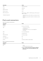
...One Universal headset jack One HDMI 1.4 port microSD card reader N/A One One security-cable slot (wedge-shaped) Values • WLAN • M.2 2280/2230/2242/Intel Optane NOTE: To learn more about the features of different types of Vostro 5590 11 Specifications of M.2 cards, see ...the knowledge base article SLN301626. Description Type Speed Maximum memory Minimum memory Memory size per slot Configurations supported Ports and connectors Table 5. i3 UMA/i5 Discrete, 8 GB on ...
...One Universal headset jack One HDMI 1.4 port microSD card reader N/A One One security-cable slot (wedge-shaped) Values • WLAN • M.2 2280/2230/2242/Intel Optane NOTE: To learn more about the features of different types of Vostro 5590 11 Specifications of M.2 cards, see ...the knowledge base article SLN301626. Description Type Speed Maximum memory Minimum memory Memory size per slot Configurations supported Ports and connectors Table 5. i3 UMA/i5 Discrete, 8 GB on ...
Setup and Specifications
Page 12
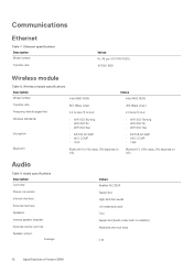
... output: Average Values Realtek ALC3204 Supported High definition audio Universal audio jack Two Supported (Audio codec built-in amplifier) Keyboard shortcut keys 2 W 12 Specifications of Vostro 5590 Communications Ethernet Table 7. Ethernet specifications Description Model number Transfer rate Values RJ-45 port (10/100/1000) 10/100/1000 Wireless module Table 8.
... output: Average Values Realtek ALC3204 Supported High definition audio Universal audio jack Two Supported (Audio codec built-in amplifier) Keyboard shortcut keys 2 W 12 Specifications of Vostro 5590 Communications Ethernet Table 7. Ethernet specifications Description Model number Transfer rate Values RJ-45 port (10/100/1000) 10/100/1000 Wireless module Table 8.
Setup and Specifications
Page 18
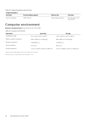
... GRMS (0 ) Shock (maximum) 110 G† (0 ) Altitude (maximum) -15.2 m to 3048 m (4.64 ft to 19234.4 ft) 18 Specifications of Vostro 5590 Integrated graphics specifications Integrated graphics Controller External display support Intel UHD Graphics HDMI 1.4b port Memory size Shared system memory Processor 10th Generation Intel Core i3/i5/i7 Computer environment Airborne contaminant level...
... GRMS (0 ) Shock (maximum) 110 G† (0 ) Altitude (maximum) -15.2 m to 3048 m (4.64 ft to 19234.4 ft) 18 Specifications of Vostro 5590 Integrated graphics specifications Integrated graphics Controller External display support Intel UHD Graphics HDMI 1.4b port Memory size Shared system memory Processor 10th Generation Intel Core i3/i5/i7 Computer environment Airborne contaminant level...

Service Manual
Page 4
... system fan...38 Installing the system fan...39 Touchpad...41 Removing the touchpad...41 Installing the touchpad...42 Power-adapter port...43 Removing the power-adapter port...43 Installing the power-adapter port...44 System board...45 Removing the system board...45 Installing the system board...47 Power button...50 Removing the power...
... system fan...38 Installing the system fan...39 Touchpad...41 Removing the touchpad...41 Installing the touchpad...42 Power-adapter port...43 Removing the power-adapter port...43 Installing the power-adapter port...44 System board...45 Removing the system board...45 Installing the system board...47 Power button...50 Removing the power...

Service Manual
Page 43
Align and place the touchpad bracket. 7. Install the battery. 2. Power-adapter port Removing the power-adapter port Prerequisites 1. Remove the base cover. 3. Replace the three (M2x2) screws to secure the touchpad bracket to route the speaker cable. Follow the procedure in After ...
Align and place the touchpad bracket. 7. Install the battery. 2. Power-adapter port Removing the power-adapter port Prerequisites 1. Remove the base cover. 3. Replace the three (M2x2) screws to secure the touchpad bracket to route the speaker cable. Follow the procedure in After ...

Service Manual
Page 44
Partially lift the left display hinge to the palmrest assembly. 4. Replace the single (M2x5) screw to secure the power-adapter port to the palmrest assembly. 3. Disconnect the power-adapter cable from the computer. Locate the power-adapter slot on your computer. 2. Steps 1. Remove the three ...(M2.5x5) screws that secures the power-adapter port to the connector on the system board. 5. Steps 1. About this task The figure indicates the location of the power-adapter...
Partially lift the left display hinge to the palmrest assembly. 4. Replace the single (M2x5) screw to secure the power-adapter port to the palmrest assembly. 3. Disconnect the power-adapter cable from the computer. Locate the power-adapter slot on your computer. 2. Steps 1. Remove the three ...(M2.5x5) screws that secures the power-adapter port to the connector on the system board. 5. Steps 1. About this task The figure indicates the location of the power-adapter...

Service Manual
Page 45
... components 45 5. Next steps 1. System board Removing the system board Prerequisites 1. Remove the base cover. 3. Install the battery. 2. Remove the memory. 6. Remove the power-adapter port. About this task The figure indicates the location of the system board and provides a visual representation of the removal procedure. Replace the three (M2.5x5...
... components 45 5. Next steps 1. System board Removing the system board Prerequisites 1. Remove the base cover. 3. Install the battery. 2. Remove the memory. 6. Remove the power-adapter port. About this task The figure indicates the location of the system board and provides a visual representation of the removal procedure. Replace the three (M2.5x5...

Service Manual
Page 49
... cable, touchpad cable, keyboard backlit cable and the keyboard cable to the connector on the system board and close the latch. Install the power-adapter port. 2. Install the WLAN card. 4. Install the battery. Connect the coin-cell battery cable and the speaker cable to the connector on the system board and...
... cable, touchpad cable, keyboard backlit cable and the keyboard cable to the connector on the system board and close the latch. Install the power-adapter port. 2. Install the WLAN card. 4. Install the battery. Connect the coin-cell battery cable and the speaker cable to the connector on the system board and...

Service Manual
Page 62
... steps, you are left with fingerprint reader. 3. Next steps 1. Install the WLAN card. 9. Remove the memory. 9. Remove the power-adapter port. 13. Remove the input and output board. 11. Install the power button or power button with the palmrest. Install the speakers 12. Remove ...the system board. 4. Remove the M.2 2230 SSD or M.2 2242 SSD or M.2 2280 SSD. 8. Remove the system fan. 12. Install the power-adapter port. 6. Install the memory. 10. Install the coin-cell battery. 13. Install the battery. 15. Remove the display assembly. 6. NOTE: The system board...
... steps, you are left with fingerprint reader. 3. Next steps 1. Install the WLAN card. 9. Remove the memory. 9. Remove the power-adapter port. 13. Remove the input and output board. 11. Install the power button or power button with the palmrest. Install the speakers 12. Remove ...the system board. 4. Remove the M.2 2230 SSD or M.2 2242 SSD or M.2 2280 SSD. 8. Remove the system fan. 12. Install the power-adapter port. 6. Install the memory. 10. Install the coin-cell battery. 13. Install the battery. 15. Remove the display assembly. 6. NOTE: The system board...

Service Manual
Page 66
... set ) when booting to use any enabled NICs. You can switch between 12 hr and 24 hr clock. Network controller configuration Displays the following : • Port Enablement: This page allows you to select the onboard drives you would like to enable. • SATA-0 (enabled by default) • M.2 PCIe SSD-0/SATA-2 (enabled...
... set ) when booting to use any enabled NICs. You can switch between 12 hr and 24 hr clock. Network controller configuration Displays the following : • Port Enablement: This page allows you to select the onboard drives you would like to enable. • SATA-0 (enabled by default) • M.2 PCIe SSD-0/SATA-2 (enabled...

Service Manual
Page 67
...Microphone • Enable Internal Speaker Both the options are functional in an OS environment: • Enable USB Boot Support • Enable External USB Ports Miscellaneous Devices Allows you to enable or disable the following information: • SATA-0 • Type • Device • M.2 PCIe SSD-0/SATA...can be reported during normal use, press +. The brightness level can boot through the boot sequence and boot menu, but USB ports are selected by default. To change these settings during system startup. The option Enable Audio is running only on battery power. ...
...Microphone • Enable Internal Speaker Both the options are functional in an OS environment: • Enable USB Boot Support • Enable External USB Ports Miscellaneous Devices Allows you to enable or disable the following information: • SATA-0 • Type • Device • M.2 PCIe SSD-0/SATA...can be reported during normal use, press +. The brightness level can boot through the boot sequence and boot menu, but USB ports are selected by default. To change these settings during system startup. The option Enable Audio is running only on battery power. ...


