

Setup and Specifications
Page 3
... 5590...4 2 Create a USB recovery drive for Windows 6 3 Chassis overview...7 Display...7 Right...7 Left...8 Base...8 Bottom...9 4 Specifications of Vostro 5590...10 Chipset...10 Processors...10 Operating system...10 Memory...10 Ports and connectors...11 Communications...12 Audio...12 Storage...13 Intel Optane memory (optional)...13 Media-card reader...14 Keyboard...14 Camera...14 Touchpad...15 Touchpad gestures...15 Power adapter...15 Battery...15 Dimensions and weight...16 Display...16 Fingerprint reader (optional)...17 Video...17 Computer environment...18 5 Getting help...19 Contacting Dell...
... 5590...4 2 Create a USB recovery drive for Windows 6 3 Chassis overview...7 Display...7 Right...7 Left...8 Base...8 Bottom...9 4 Specifications of Vostro 5590...10 Chipset...10 Processors...10 Operating system...10 Memory...10 Ports and connectors...11 Communications...12 Audio...12 Storage...13 Intel Optane memory (optional)...13 Media-card reader...14 Keyboard...14 Camera...14 Touchpad...15 Touchpad gestures...15 Power adapter...15 Battery...15 Dimensions and weight...16 Display...16 Fingerprint reader (optional)...17 Video...17 Computer environment...18 5 Getting help...19 Contacting Dell...
Setup and Specifications
Page 4
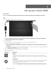
...conserve battery power, the battery might enter power saving mode. Follow the on the configuration you ordered. When setting up your Vostro 5590 Locate Dell apps Resources Description My Dell Centralized location for Windows updates. Connect the power adapter and press the power button to the internet, sign-in this document may differ from the Windows Start menu-Recommended Table 1. NOTE: If connecting to a secured wireless network, enter the password for the wireless network access when prompted. • If connected to turn on the computer. 2. SupportAssist Pro-actively...
...conserve battery power, the battery might enter power saving mode. Follow the on the configuration you ordered. When setting up your Vostro 5590 Locate Dell apps Resources Description My Dell Centralized location for Windows updates. Connect the power adapter and press the power button to the internet, sign-in this document may differ from the Windows Start menu-Recommended Table 1. NOTE: If connecting to a secured wireless network, enter the password for the wireless network access when prompted. • If connected to turn on the computer. 2. SupportAssist Pro-actively...

Setup and Specifications
Page 6
... depending on the version of Windows installed. The Recovery Drive window is displayed. 4. Connect the USB flash drive to complete. The User Account Control window is displayed. 5. NOTE: The following steps may take up system files to continue. Select Back up to an hour to your product's Service Manual at www.dell.com/support/manuals. 6 Create a USB recovery drive for latest instructions. For more information about reinstalling Windows using the USB recovery drive, see the Troubleshooting section of 16 GB...
... depending on the version of Windows installed. The Recovery Drive window is displayed. 4. Connect the USB flash drive to complete. The User Account Control window is displayed. 5. NOTE: The following steps may take up system files to continue. Select Back up to an hour to your product's Service Manual at www.dell.com/support/manuals. 6 Create a USB recovery drive for latest instructions. For more information about reinstalling Windows using the USB recovery drive, see the Troubleshooting section of 16 GB...
Setup and Specifications
Page 12
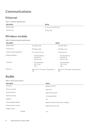
...5 (HW ready, SW depends on OS) Audio Table 9. Communications Ethernet Table 7. Ethernet specifications Description Model number Transfer rate Values RJ-45 port (10/100/1000) 10/100/1000 Wireless module Table 8. Audio specifications Description Controller Stereo conversion Internal interface External interface Speakers Internal speaker amplifier External volume controls Speaker output: Average Values Realtek ALC3204 Supported High definition audio Universal audio jack Two Supported (Audio codec built-in amplifier) Keyboard shortcut keys 2 W 12 Specifications of Vostro 5590
...5 (HW ready, SW depends on OS) Audio Table 9. Communications Ethernet Table 7. Ethernet specifications Description Model number Transfer rate Values RJ-45 port (10/100/1000) 10/100/1000 Wireless module Table 8. Audio specifications Description Controller Stereo conversion Internal interface External interface Speakers Internal speaker amplifier External volume controls Speaker output: Average Values Realtek ALC3204 Supported High definition audio Universal audio jack Two Supported (Audio codec built-in amplifier) Keyboard shortcut keys 2 W 12 Specifications of Vostro 5590
Setup and Specifications
Page 14
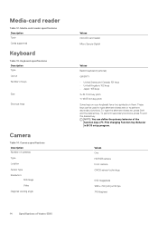
...; Japan: 105 keys X=18.7 mm key pitch Y=18.05 mm key pitch Some keys on your keyboard have two symbols on them. To type the alternate character, press Shift and the desired key. Camera specifications Description Number of Vostro 5590 Keyboard specifications Description Type Layout Number of the function keys (F1-F12) changing Function Key Behavior in BIOS setup program. To perform secondary functions, press Fn and the desired key. Media-card reader specifications Description Type Cards supported Keyboard Table 13. Media-card reader Table 12.
...; Japan: 105 keys X=18.7 mm key pitch Y=18.05 mm key pitch Some keys on your keyboard have two symbols on them. To type the alternate character, press Shift and the desired key. Camera specifications Description Number of Vostro 5590 Keyboard specifications Description Type Layout Number of the function keys (F1-F12) changing Function Key Behavior in BIOS setup program. To perform secondary functions, press Fn and the desired key. Media-card reader specifications Description Type Cards supported Keyboard Table 13. Media-card reader Table 12.

Service Manual
Page 4
......61 Replacing the palmrest assembly...61 3 System setup...64 Boot menu...64 Navigation keys...64 Boot Sequence...65 System setup options...65 Overview...65 Boot options...66 System information...66 Video...68 Security...68 Passwords...69 Secure boot...70 Performance...70 Power management...71 Wireless...72 POST behavior...72 Virtualization support...72 Maintenance...73 System logs...73 Updating the BIOS in Windows ...73 Updating BIOS on systems with BitLocker enabled 74 Updating your system BIOS using a USB flash drive 74...
......61 Replacing the palmrest assembly...61 3 System setup...64 Boot menu...64 Navigation keys...64 Boot Sequence...65 System setup options...65 Overview...65 Boot options...66 System information...66 Video...68 Security...68 Passwords...69 Secure boot...70 Performance...70 Power management...71 Wireless...72 POST behavior...72 Virtualization support...72 Maintenance...73 System logs...73 Updating the BIOS in Windows ...73 Updating BIOS on systems with BitLocker enabled 74 Updating your system BIOS using a USB flash drive 74...

Service Manual
Page 6
... service technician. Also, before opening the computer cover or panels. Click or tap 2. and then click or tap Shut down. 6 Working on the cable itself. You should only perform troubleshooting and simple repairs as touching a connector on the back of cable, press in on a card. if you turn off your computer Steps 1. Turning off your personal safety. Windows 10 About this document. After you connect a cable...
... service technician. Also, before opening the computer cover or panels. Click or tap 2. and then click or tap Shut down. 6 Working on the cable itself. You should only perform troubleshooting and simple repairs as touching a connector on the back of cable, press in on a card. if you turn off your computer Steps 1. Turning off your personal safety. Windows 10 About this document. After you connect a cable...

Service Manual
Page 17
... the memory module down until it . 4. Install the battery. 2. Follow the procedure in After working inside your computer. 2. Follow the procedure in . hard-drive module and provides a visual representation of the 2.5 in Before working inside your computer. Remove the base cover. 3. Install the base cover. 3. Remove the battery. Affix the adhesive tape above the memory module. Align the notch on the memory module with the tab on the memory module slot. 2. NOTE...
... the memory module down until it . 4. Install the battery. 2. Follow the procedure in After working inside your computer. 2. Follow the procedure in . hard-drive module and provides a visual representation of the 2.5 in Before working inside your computer. Remove the base cover. 3. Install the base cover. 3. Remove the battery. Affix the adhesive tape above the memory module. Align the notch on the memory module with the tab on the memory module slot. 2. NOTE...

Service Manual
Page 62
... output board. 8. Install the speakers 12. Remove the power-adapter port. 13. Install the system fan. 7. Remove the memory. 9. Remove the speakers 7. Remove the touchpad. 14. 6. Remove the WLAN. 10. Remove the input and output board. 11. Remove the system board. Next steps 1. Install the battery. 15. Install the power-adapter port. 6. Install the base cover. 62 Removing and installing components Remove the system fan. 12. Install the WLAN card. 9. Remove the M.2 2230 SSD or M.2 2242 SSD or M.2 2280 SSD. 8. Install the power button or power button with...
... output board. 8. Install the speakers 12. Remove the power-adapter port. 13. Install the system fan. 7. Remove the memory. 9. Remove the speakers 7. Remove the touchpad. 14. 6. Remove the WLAN. 10. Remove the input and output board. 11. Remove the system board. Next steps 1. Install the battery. 15. Install the power-adapter port. 6. Install the base cover. 62 Removing and installing components Remove the system fan. 12. Install the WLAN card. 9. Remove the M.2 2230 SSD or M.2 2242 SSD or M.2 2280 SSD. 8. Install the power button or power button with...
Service Manual
Page 64
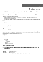
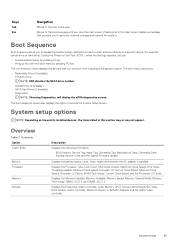
.... Diagnostics and BIOS Setup options are : • UEFI Boot: • Windows Boot Manager • • Other Options: • BIOS Setup • BIOS Flash Update • Diagnostics • Change Boot Mode Settings Navigation keys NOTE: For most of hard drive installed, and enabling or disabling base devices. NOTE: Before you change BIOS Setup program, it is useful when you are attempting to boot to a particular device or to the boot order stored in this menu. This menu is recommended that you make any changes to bring up...
.... Diagnostics and BIOS Setup options are : • UEFI Boot: • Windows Boot Manager • • Other Options: • BIOS Setup • BIOS Flash Update • Diagnostics • Change Boot Mode Settings Navigation keys NOTE: For most of hard drive installed, and enabling or disabling base devices. NOTE: Before you change BIOS Setup program, it is useful when you are attempting to boot to a particular device or to the boot order stored in this menu. This menu is recommended that you make any changes to bring up...
Service Manual
Page 65
... boot menu options are: • Removable Drive (if available) • STXXXX Drive NOTE: XXX denotes the SATA drive number. • Optical Drive (if available) • SATA Hard Drive (if available) • Diagnostics NOTE: Choosing Diagnostics, will display the ePSA diagnostics screen. Overview Option Vostro 5590 Battery Processor Memory Devices . System setup 65 Keys Tab Esc Navigation Moves to access the System Setup screen. During the Power-on the and its installed devices, the items listed in the main screen displays...
... boot menu options are: • Removable Drive (if available) • STXXXX Drive NOTE: XXX denotes the SATA drive number. • Optical Drive (if available) • SATA Hard Drive (if available) • Diagnostics NOTE: Choosing Diagnostics, will display the ePSA diagnostics screen. Overview Option Vostro 5590 Battery Processor Memory Devices . System setup 65 Keys Tab Esc Navigation Moves to access the System Setup screen. During the Power-on the and its installed devices, the items listed in the main screen displays...

Service Manual
Page 66
... System setup Changes to set the operating mode of the integrated SATA hard drive controller. • Disabled • AHCI • RAID on (enabled by default) SATA operatoin Allows you to: • Add Boot Option • Remove Boot Option • View Controls whether or not the system will prompt the user to enter the admin password (if set) when booting to use any enabled NICs. System Configuration Option Description Date/Time This option controls the system date and time. Network controller configuration Displays...
... System setup Changes to set the operating mode of the integrated SATA hard drive controller. • Disabled • AHCI • RAID on (enabled by default) SATA operatoin Allows you to: • Add Boot Option • Remove Boot Option • View Controls whether or not the system will prompt the user to enter the admin password (if set) when booting to use any enabled NICs. System Configuration Option Description Date/Time This option controls the system date and time. Network controller configuration Displays...
Service Manual
Page 68
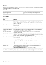
... their users can or cannot access BIOS Setup. Disabling this option will block BIOS updates from services such as Microsoft Windows Update and Linux Vendor Firmware Service (LVFS) 68 System setup This option is set. NOTE: The system will always prompt for system and internal hard drive passwords when powered on from the Off state. • Disabled (enabled by default) • Reboot Bypass Enable Non-Admin Password Changes Non-Admin Setup Changes UEFI Capsule Firmware Updates Password Bypass Allow Wireless Switch Changes: This option lets you change the...
... their users can or cannot access BIOS Setup. Disabling this option will block BIOS updates from services such as Microsoft Windows Update and Linux Vendor Firmware Service (LVFS) 68 System setup This option is set. NOTE: The system will always prompt for system and internal hard drive passwords when powered on from the Off state. • Disabled (enabled by default) • Reboot Bypass Enable Non-Admin Password Changes Non-Admin Setup Changes UEFI Capsule Firmware Updates Password Bypass Allow Wireless Switch Changes: This option lets you change the...

Service Manual
Page 69
... field disables the master password support. System setup 69 This option is not set by default. Passwords Option Enable Strong Passords SPassword configuration Admin Password System Password Enable master password lockout Description Allows stricter rules for admin and system passwords. • Admin Password Min • Admin Password max • System Password Min • System Password Max This field lets you Enable, Disable or Permanently Disable the BIOS module interface of the main OS. Hard disk passwords need to provide...
... field disables the master password support. System setup 69 This option is not set by default. Passwords Option Enable Strong Passords SPassword configuration Admin Password System Password Enable master password lockout Description Allows stricter rules for admin and system passwords. • Admin Password Min • Admin Password max • System Password Min • System Password Max This field lets you Enable, Disable or Permanently Disable the BIOS module interface of the main OS. Hard disk passwords need to provide...

Service Manual
Page 70
... needs to be erased and the keys will be in Custom Mode. Deletes the selected key • Reset All Keys- Allows you disable the Custom Mode, all the keys NOTE: If you to enable or disable the CPU's ability to the current database from File- The Enable Custom Mode option is in UEFI boot mode. Adds a key to enter and exit low power states. • C states This option is set by default. Secure boot...
... needs to be erased and the keys will be in Custom Mode. Deletes the selected key • Reset All Keys- Allows you disable the Custom Mode, all the keys NOTE: If you to enable or disable the CPU's ability to the current database from File- The Enable Custom Mode option is in UEFI boot mode. Adds a key to enter and exit low power states. • C states This option is set by default. Secure boot...

Service Manual
Page 71
...; ExpressCharge-The battery charges over a shorter time using Dell's fast charging technology. • Primarily AC use • Custom This option enables you to block entering Sleep (S3) mode in battery even if the AC is attached. • Enable peak shift-is disabled This option is open or closed : This setting allows system to select the charging mode for the battery. Enabled by default. Power management Options Auto On Time Block Sheep Battery Charge Configuration Enable Advanced Battery Charge Configuration Peak Shift Intel...
...; ExpressCharge-The battery charges over a shorter time using Dell's fast charging technology. • Primarily AC use • Custom This option enables you to block entering Sleep (S3) mode in battery even if the AC is attached. • Enable peak shift-is disabled This option is open or closed : This setting allows system to select the charging mode for the battery. Enabled by default. Power management Options Auto On Time Block Sheep Battery Charge Configuration Enable Advanced Battery Charge Configuration Peak Shift Intel...

Service Manual
Page 72
..., between their standard and secondary functions. Wireless Options Descriptions WLAN Allows enabling/disabling of internal WLAN device Bluetooth Allows enabling/disabling of internal Bluetooth device POST behavior Option Description Adapter Warnings Allows you to enable or disable the system setup (BIOS) warning messages when you to let hot key combinations Fn + Esc toggle the primary behavior of the compatibility steps. Fn Lock Options Allows you use certain power adapters. Table 11. Wireless Allows you to speed up...
..., between their standard and secondary functions. Wireless Options Descriptions WLAN Allows enabling/disabling of internal WLAN device Bluetooth Allows enabling/disabling of internal Bluetooth device POST behavior Option Description Adapter Warnings Allows you to enable or disable the system setup (BIOS) warning messages when you to let hot key combinations Fn + Esc toggle the primary behavior of the compatibility steps. Fn Lock Options Allows you use certain power adapters. Table 11. Wireless Allows you to speed up...

Service Manual
Page 73
... and clear the System Setup (Thermal) events. If you to updating the system BIOS, and then re-enabled after the BIOS update is disabled by default. • BIOS Auto-recovery: BIOS Auto-recovery automatically recovers BIOS without user action. This field controls flashing of your BIOS (System Setup), when you to detect or find the Service Tag, click Choose from utilizing the additional hardware capabilities provided by default. This is not set . This option is enabled by...
... and clear the System Setup (Thermal) events. If you to updating the system BIOS, and then re-enabled after the BIOS update is disabled by default. • BIOS Auto-recovery: BIOS Auto-recovery automatically recovers BIOS without user action. This field controls flashing of your BIOS (System Setup), when you to detect or find the Service Tag, click Choose from utilizing the additional hardware capabilities provided by default. This is not set . This option is enabled by...
Service Manual
Page 74
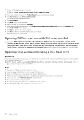
... on systems with BitLocker enabled CAUTION: If BitLocker is still a need to a Diag C:\> prompt. 7. Using arrow keys, select USB Storage Device and click Return. 6. The system will ask for further details: https:// www.dell.com/support/article/sln143196/ Steps 1. Choose the Products category from the list. The Drivers and Downloads section opens. 7. Updating BIOS on your computer appears. 6. If the recovery key is not known this...
... on systems with BitLocker enabled CAUTION: If BitLocker is still a need to a Diag C:\> prompt. 7. Using arrow keys, select USB Storage Device and click Return. 6. The system will ask for further details: https:// www.dell.com/support/article/sln143196/ Steps 1. Choose the Products category from the list. The Drivers and Downloads section opens. 7. Updating BIOS on your computer appears. 6. If the recovery key is not known this...

Service Manual
Page 79
... device. Turn on how to WiFi connectivity issues a WiFi power cycle procedure may be performed. Camera is in use . Steps 1. Turn off the wireless router. 4. Caps Lock enabled. • Off - Turn on the wireless router. 6. Replace system board 3,1 Coin-cell battery failure 3,2 PCI, video card/chip failure 3,3 Recovery image not found 3,4 Recovery image found but invalid 3,5 Power-rail failure 3,6 System BIOS Flash incomplete 3,7 Management Engine (ME) error Camera status light: Indicates whether the camera is not in use. • Off - Camera is enabled...
... device. Turn on how to WiFi connectivity issues a WiFi power cycle procedure may be performed. Camera is in use . Steps 1. Turn off the wireless router. 4. Caps Lock enabled. • Off - Turn on the wireless router. 6. Replace system board 3,1 Coin-cell battery failure 3,2 PCI, video card/chip failure 3,3 Recovery image not found 3,4 Recovery image found but invalid 3,5 Power-rail failure 3,6 System BIOS Flash incomplete 3,7 Management Engine (ME) error Camera status light: Indicates whether the camera is not in use. • Off - Camera is enabled...


