Service Manual
Page 6
... all attached devices are turned off. For additional safety best practices information, see the Regulatory Compliance Homepage CAUTION: Many repairs may only be replaced or, if purchased separately, installed by the online or telephone service and support team. Read and follow the safety instructions that the computer and all power sources before connecting to the power source. Hold a card by its edges...
... all attached devices are turned off. For additional safety best practices information, see the Regulatory Compliance Homepage CAUTION: Many repairs may only be replaced or, if purchased separately, installed by the online or telephone service and support team. Read and follow the safety instructions that the computer and all power sources before connecting to the power source. Hold a card by its edges...

Service Manual
Page 7
After working inside your computer CAUTION: Leaving stray or loose screws inside your computer may severely damage your computer. 1 Replace all screws and ensure that no stray screws remain inside your computer. 2 Connect any external devices, peripherals, or cables you removed before working on your computer. 3 Replace any media cards, discs, or any other parts that you removed before working on your computer. 4 Connect your computer and all attached devices to their electrical outlets. 5 Turn on your computer. Working on your computer 7
After working inside your computer CAUTION: Leaving stray or loose screws inside your computer may severely damage your computer. 1 Replace all screws and ensure that no stray screws remain inside your computer. 2 Connect any external devices, peripherals, or cables you removed before working on your computer. 3 Replace any media cards, discs, or any other parts that you removed before working on your computer. 4 Connect your computer and all attached devices to their electrical outlets. 5 Turn on your computer. Working on your computer 7
Service Manual
Page 9
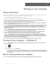
... an HDMI-connected TV with the advantages. Curved edge Memory Errors Memory errors on . Troubleshoot for a separate audio cable • 3D - NOTE: The HDMI 1.4 will provide 5.1 channel audio support. Adds high-speed networking to an HDMI link, allowing users to optimize picture settings based on the bottom of their IP-enabled devices without a separate Ethernet cable • Audio Return Channel - Real-time signaling of content types between any compatible digital audio/video source...
... an HDMI-connected TV with the advantages. Curved edge Memory Errors Memory errors on . Troubleshoot for a separate audio cable • 3D - NOTE: The HDMI 1.4 will provide 5.1 channel audio support. Adds high-speed networking to an HDMI link, allowing users to optimize picture settings based on the bottom of their IP-enabled devices without a separate Ethernet cable • Audio Return Channel - Real-time signaling of content types between any compatible digital audio/video source...

Service Manual
Page 10
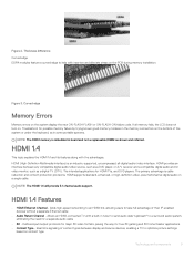
... video for additional color models used in A/V systems • HDMI supports communication between host computers and peripheral devices like mice, keyboards, external drivers, and printers. New cables and connectors for automotive video systems, designed to the consumers' demands with about 6 billion devices sold, and yet the need for new transfer types • Backward USB 2.0 compatibility • New connectors and cable The topics below . It dramatically simplified the connection between the video...
... video for additional color models used in A/V systems • HDMI supports communication between host computers and peripheral devices like mice, keyboards, external drivers, and printers. New cables and connectors for automotive video systems, designed to the consumers' demands with about 6 billion devices sold, and yet the need for new transfer types • Backward USB 2.0 compatibility • New connectors and cable The topics below . It dramatically simplified the connection between the video...

Service Manual
Page 17
... that secures the battery to default. CAUTION: Removing the coin-cell battery resets the BIOS setup program's settings to the system board and palm-rest and keyboard assembly. 1 Install the base cover. 2 Follow the procedure in Before working inside your computer. The following image indicates the location of the coin-cell battery and provides a visual representation of the removal procedure. 1 Connect the battery cable to the system board. 2 Replace the four screws...
... that secures the battery to default. CAUTION: Removing the coin-cell battery resets the BIOS setup program's settings to the system board and palm-rest and keyboard assembly. 1 Install the base cover. 2 Follow the procedure in Before working inside your computer. The following image indicates the location of the coin-cell battery and provides a visual representation of the removal procedure. 1 Connect the battery cable to the system board. 2 Replace the four screws...
Service Manual
Page 66
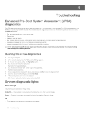
... corner. The embedded system diagnostics provides a set of problems encountered during testing NOTE: Some tests for specific devices require user interaction. Solid white - System diagnostic lights Battery-status light Indicates the power and battery-charge status. 4 Troubleshooting Enhanced Pre-Boot System Assessment (ePSA) diagnostics The ePSA diagnostics (also known as the Dell logo appears. 3 On the boot menu screen, select the Diagnostics option. 4 Click the arrow at the computer...
... corner. The embedded system diagnostics provides a set of problems encountered during testing NOTE: Some tests for specific devices require user interaction. Solid white - System diagnostic lights Battery-status light Indicates the power and battery-charge status. 4 Troubleshooting Enhanced Pre-Boot System Assessment (ePSA) diagnostics The ePSA diagnostics (also known as the Dell logo appears. 3 On the boot menu screen, select the Diagnostics option. 4 Click the arrow at the computer...
Service Manual
Page 67
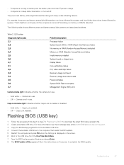
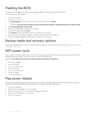
... USB drive to the computer that needs the BIOS update. 5 Restart the computer and press F12 when the Dell logo is displayed on the screen to download the latest BIOS setup program file. 2 Create a bootable USB drive. Camera is not in sleep state, hibernation, or turned off indicating no memory or RAM is enabled or disabled. • Solid white - Flashing BIOS (USB key) 1 Follow the procedure from the One Time Boot Menu. 7 Type the BIOS setup program filename and press Enter. 8 The BIOS Update Utility...
... USB drive to the computer that needs the BIOS update. 5 Restart the computer and press F12 when the Dell logo is displayed on the screen to download the latest BIOS setup program file. 2 Create a bootable USB drive. Camera is not in sleep state, hibernation, or turned off indicating no memory or RAM is enabled or disabled. • Solid white - Flashing BIOS (USB key) 1 Follow the procedure from the One Time Boot Menu. 7 Type the BIOS setup program filename and press Enter. 8 The BIOS Update Utility...
Service Manual
Page 68
... manually browse for recovering Windows operating system on your Dell PC. The following procedure provides the instructions on your computer. 6 Scroll down the page and expand BIOS. 7 Click Download to download the latest version of your computer model. 4 Click Drivers & downloads > Find it has been powered off your computer. 2 Disconnect the power adapter from your computer. 3 Press and hold the power button for 30 seconds. 5 Turn on the wireless router. 6 Turn...
... manually browse for recovering Windows operating system on your Dell PC. The following procedure provides the instructions on your computer. 6 Scroll down the page and expand BIOS. 7 Click Download to download the latest version of your computer model. 4 Click Drivers & downloads > Find it has been powered off your computer. 2 Disconnect the power adapter from your computer. 3 Press and hold the power button for 30 seconds. 5 Turn on the wireless router. 6 Turn...

Setup and specifications guide
Page 3
... computer...5 2 Create a USB recovery drive for Windows...7 3 Chassis overview...8 Display view...8 Left view...9 Right view...9 Palmrest view...10 Bottom view...10 Keyboard shortcuts...11 4 Technical specifications...12 System information...12 Processor...12 Memory...12 Storage...13 System board connectors...13 Media card-reader...13 Audio...14 Video card...14 Camera...15 Wireless...15 Ports and connectors...15 Display...16 Keyboard...16 Touchpad...17 Fingerprint reader-optional...17 Operating system...18 Battery...18 Power adapter...18 Sensor and control specifications...19...
... computer...5 2 Create a USB recovery drive for Windows...7 3 Chassis overview...8 Display view...8 Left view...9 Right view...9 Palmrest view...10 Bottom view...10 Keyboard shortcuts...11 4 Technical specifications...12 System information...12 Processor...12 Memory...12 Storage...13 System board connectors...13 Media card-reader...13 Audio...14 Video card...14 Camera...15 Wireless...15 Ports and connectors...15 Display...16 Keyboard...16 Touchpad...17 Fingerprint reader-optional...17 Operating system...18 Battery...18 Power adapter...18 Sensor and control specifications...19...
Setup and specifications guide
Page 7
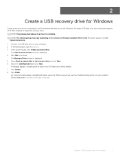
... Windows Create a recovery drive to troubleshoot and fix problems that all data in the USB flash drive will be deleted. 7 Click Create. 8 Click Finish. Create a USB recovery drive for latest instructions. 1 Connect the USB flash drive to continue. Refer to the Microsoft support site for Windows 7 The Recovery Drive window is displayed. 4 Click Yes to your product's Service Manual at www.dell.com/support/manuals. A message appears, indicating that may occur with a minimum capacity of 16 GB is required to create the recovery drive. The User...
... Windows Create a recovery drive to troubleshoot and fix problems that all data in the USB flash drive will be deleted. 7 Click Create. 8 Click Finish. Create a USB recovery drive for latest instructions. 1 Connect the USB flash drive to continue. Refer to the Microsoft support site for Windows 7 The Recovery Drive window is displayed. 4 Click Yes to your product's Service Manual at www.dell.com/support/manuals. A message appears, indicating that may occur with a minimum capacity of 16 GB is required to create the recovery drive. The User...

Setup and specifications guide
Page 11
... Fn + 12 Fn + Ctrl Description Toggle Fn-key lock Mute audio Decrease volume Increase volume Play / Pause Turn on the keyboard language configuration. Keys that are used for shortcuts remain the same across all language configurations. 1 Left speaker 3 Right speaker Keyboard shortcuts 2 Service Tag label NOTE: Keyboard characters may differ depending on /off keyboard backlight Decrease brightness Increase brightness Switch to external display Print screen Home End Open application menu Chassis overview 11
... Fn + 12 Fn + Ctrl Description Toggle Fn-key lock Mute audio Decrease volume Increase volume Play / Pause Turn on the keyboard language configuration. Keys that are used for shortcuts remain the same across all language configurations. 1 Left speaker 3 Right speaker Keyboard shortcuts 2 Service Tag label NOTE: Keyboard characters may differ depending on /off keyboard backlight Decrease brightness Increase brightness Switch to external display Print screen Home End Open application menu Chassis overview 11
Setup and specifications guide
Page 22
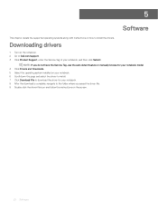
... details the supported operating systems along with instructions on the screen. 22 Software Downloading drivers 1 Turn on the notebook. 2 Go to Dell.com/support. 3 Click Product Support, enter the Service Tag of your notebook. 8 After the download is complete, navigate to the folder where you do not have the Service Tag, use the auto detect feature or manually browse for your notebook model. 4 Click Drivers and Downloads. 5 Select the operating system installed on your notebook. 6 Scroll down...
... details the supported operating systems along with instructions on the screen. 22 Software Downloading drivers 1 Turn on the notebook. 2 Go to Dell.com/support. 3 Click Product Support, enter the Service Tag of your notebook. 8 After the download is complete, navigate to the folder where you do not have the Service Tag, use the auto detect feature or manually browse for your notebook model. 4 Click Drivers and Downloads. 5 Select the operating system installed on your notebook. 6 Scroll down...
Setup and specifications guide
Page 23
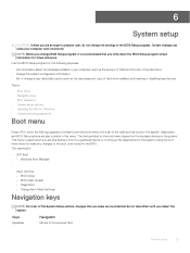
... the boot order stored in Windows • System and setup password Boot menu Press when the Dell logo appears to bring up the diagnostics for the system. BIOS Setup - Certain changes can make your computer, such as the user password, type of hard drive installed, and enabling or disabling base devices. Windows Boot Manager • • Other Options: - Diagnostics - Using the boot menu does not make are : • UEFI Boot: - Topics: • Boot menu • Navigation keys • Boot Sequence • System setup options • Updating the BIOS...
... the boot order stored in Windows • System and setup password Boot menu Press when the Dell logo appears to bring up the diagnostics for the system. BIOS Setup - Certain changes can make your computer, such as the user password, type of hard drive installed, and enabling or disabling base devices. Windows Boot Manager • • Other Options: - Diagnostics - Using the boot menu does not make are : • UEFI Boot: - Topics: • Boot menu • Navigation keys • Boot Sequence • System setup options • Updating the BIOS...

Setup and specifications guide
Page 24
... System Setup-defined boot device order and boot directly to a specific device (for example: optical drive or hard drive). Displays the Asset Tag of the computer. Displays the Service Tag of the computer. Keys Down arrow Enter Spacebar Tab Esc Navigation Moves to save any unsaved changes and restarts the system. The boot menu options are listed in the main screen displays a message that you can : • Access System Setup by pressing F2 key •...
... System Setup-defined boot device order and boot directly to a specific device (for example: optical drive or hard drive). Displays the Asset Tag of the computer. Displays the Service Tag of the computer. Keys Down arrow Enter Spacebar Tab Esc Navigation Moves to save any unsaved changes and restarts the system. The boot menu options are listed in the main screen displays a message that you can : • Access System Setup by pressing F2 key •...

Setup and specifications guide
Page 26
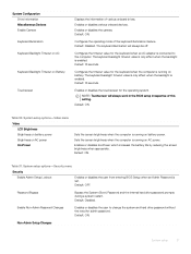
... or disables UEFI Network Stack. Enable Internal Speaker Enables or disables internal speaker. USB Configuration Enable Boot Support Enable External USB Ports SATA Operation Enables or disables booting from the F12 boot menu. Default: ON. Default: ON. Configures operating mode of this computer. Default: RAID. Default: OFF. Enables or disables advanced BIOS settings. Boot Mode Boot Mode: UEFI only Enable Boot Devices Boot Sequence BIOS Setup Advanced Mode Displays the boot mode of the integrated SATA hard drive controller. SATA is configured to report hard drive errors.
... or disables UEFI Network Stack. Enable Internal Speaker Enables or disables internal speaker. USB Configuration Enable Boot Support Enable External USB Ports SATA Operation Enables or disables booting from the F12 boot menu. Default: ON. Default: ON. Configures operating mode of this computer. Default: RAID. Default: OFF. Enables or disables advanced BIOS settings. Boot Mode Boot Mode: UEFI only Enable Boot Devices Boot Sequence BIOS Setup Advanced Mode Displays the boot mode of the integrated SATA hard drive controller. SATA is configured to report hard drive errors.
Setup and specifications guide
Page 27
... keyboard when an AC adapter is set. Default: Disabled. System setup options-Security menu Security Enable Admin Setup Lockout Enables or disables the user from entering BIOS Setup when an Admin Password is connected to change the system and hard drive password without the need for the keyboard when the computer is running on Battery Touchscreen Displays the information of various onboard drives. Default: ON. System Configuration Drive Information Miscellaneous Devices Enable Camera Keyboard Illumination Keyboard Backlight Timeout on AC Keyboard Backlight Timeout on AC power...
... keyboard when an AC adapter is set. Default: Disabled. System setup options-Security menu Security Enable Admin Setup Lockout Enables or disables the user from entering BIOS Setup when an Admin Password is connected to change the system and hard drive password without the need for the keyboard when the computer is running on Battery Touchscreen Displays the information of various onboard drives. Default: ON. System Configuration Drive Information Miscellaneous Devices Enable Camera Keyboard Illumination Keyboard Backlight Timeout on AC Keyboard Backlight Timeout on AC power...

Setup and specifications guide
Page 30
... is opened. Bluetooth Default: ON. Fastboot Configures the speed of the day to power up from Standby mode. Default: ON. Default: ON. Power Management Enable Advanced Battery Charge Configuration Block Sleep Enable USB Wake Support Enable Intel Speed Shift Technology Lid Switch Enables Advanced Battery Charge Configuration from entering Sleep (S3) mode in the operating system. Enables the USB devices to Sleep. Default: OFF. Default: 0 seconds. As a result, the setting does not affect the Wireless Switch behavior. System setup options-POST Behavior menu...
... is opened. Bluetooth Default: ON. Fastboot Configures the speed of the day to power up from Standby mode. Default: ON. Default: ON. Power Management Enable Advanced Battery Charge Configuration Block Sleep Enable USB Wake Support Enable Intel Speed Shift Technology Lid Switch Enables Advanced Battery Charge Configuration from entering Sleep (S3) mode in the operating system. Enables the USB devices to Sleep. Default: OFF. Default: 0 seconds. As a result, the setting does not affect the Wireless Switch behavior. System setup options-POST Behavior menu...

Setup and specifications guide
Page 31
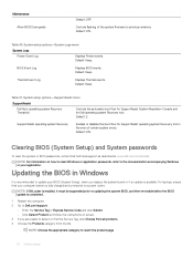
... connected to Enabled. System setup options-Maintenance menu Maintenance Asset Tag Creates a system Asset Tag that provides virtualization for Direct I /O. Default: OFF. Once set to the motherboard on encountering a warning or error during boot. Enabled or disabled the computer to fix the main BIOS block and cannot work in BIOS, the Asset Tag cannot be used by an IT administrator to perform Virtualization Technology for memory map I /O (VT-d). This feature requires BIOS Recovery...
... connected to Enabled. System setup options-Maintenance menu Maintenance Asset Tag Creates a system Asset Tag that provides virtualization for Direct I /O. Default: OFF. Once set to the motherboard on encountering a warning or error during boot. Enabled or disabled the computer to fix the main BIOS block and cannot work in BIOS, the Asset Tag cannot be used by an IT administrator to perform Virtualization Technology for memory map I /O (VT-d). This feature requires BIOS Recovery...
Setup and specifications guide
Page 32
... operating system Recovery Enables or disables the boot flow for Dell operating system Recovery tool. Clearing BIOS (System Setup) and System passwords To clear the system or BIOS passwords, contact Dell technical support as described at www.dell.com/contactdell. NOTE: For information on screen. 3 If you replace the system board or if an update is fully charged and connected to a power outlet. NOTE: Choose the appropriate category to previous revisions. System setup options-SupportAssist menu SupportAssist Dell Auto operating...
... operating system Recovery Enables or disables the boot flow for Dell operating system Recovery tool. Clearing BIOS (System Setup) and System passwords To clear the system or BIOS passwords, contact Dell technical support as described at www.dell.com/contactdell. NOTE: For information on screen. 3 If you replace the system board or if an update is fully charged and connected to a power outlet. NOTE: Choose the appropriate category to previous revisions. System setup options-SupportAssist menu SupportAssist Dell Auto operating...
Setup and specifications guide
Page 33
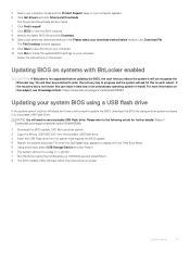
... typing the full filename e.g. Follow the instructions on screen. System setup 33 If the recovery key is not known this subject, see Knowledge Article: https://www.dell.com/support/article/sln153694 Updating your computer. You will then be prompted to enter the recovery key to progress and the system will not recognize the BitLocker key. O9010A12.EXE onto the bootable USB Flash drive. 3 Insert the USB Flash drive into Windows...
... typing the full filename e.g. Follow the instructions on screen. System setup 33 If the recovery key is not known this subject, see Knowledge Article: https://www.dell.com/support/article/sln153694 Updating your computer. You will then be prompted to enter the recovery key to progress and the system will not recognize the BitLocker key. O9010A12.EXE onto the bootable USB Flash drive. 3 Insert the USB Flash drive into Windows...


