
Service Manual
Page 1
....; Microsoft, Windows, Windows Vista, and the Windows Vista start button logo are not applicable. Dell™ Vostro™ 420/220/220s Service Manual Troubleshooting Working on Your Computer Computer Cover Bezel Chassis Support Bracket PCI and PCI Express Cards Drives I/O Panel Fan Processor Heat Sink/Fan Assembly Memory Module(s) Power Supply Coin-Cell Battery...
....; Microsoft, Windows, Windows Vista, and the Windows Vista start button logo are not applicable. Dell™ Vostro™ 420/220/220s Service Manual Troubleshooting Working on Your Computer Computer Cover Bezel Chassis Support Bracket PCI and PCI Express Cards Drives I/O Panel Fan Processor Heat Sink/Fan Assembly Memory Module(s) Power Supply Coin-Cell Battery...

Service Manual
Page 2
...computer. Rotate the bezel away from the computer to release the hooks on the opposite edge of the front of the bezel from the chassis. 1 clips (4) 2 bezel Replacing the Bezel 1. For additional safety best practices information, see Removing the Computer Cover). 3. Removing ...only and may not represent your particular computer precisely. the illustrations provided are for the Vostro 420, Vostro 220, and Vostro 220s computers; Back to Contents Page Bezel Dell™ Vostro™ 420/220/220s Service Manual Removing the Bezel Replacing the Bezel CAUTION: Before working inside your ...
...computer. Rotate the bezel away from the computer to release the hooks on the opposite edge of the front of the bezel from the chassis. 1 clips (4) 2 bezel Replacing the Bezel 1. For additional safety best practices information, see Removing the Computer Cover). 3. Removing ...only and may not represent your particular computer precisely. the illustrations provided are for the Vostro 420, Vostro 220, and Vostro 220s computers; Back to Contents Page Bezel Dell™ Vostro™ 420/220/220s Service Manual Removing the Bezel Replacing the Bezel CAUTION: Before working inside your ...

Service Manual
Page 4
... remove the bracket before removing the cover. Back to Contents Page Chassis Support Bracket Dell™ Vostro™ 420/220/220s Service Manual Removing the Chassis Support Bracket Replacing the Chassis Support Bracket CAUTION: Before working inside your computer, read the safety information that secures the chassis support bracket. 4. CAUTION: To guard against electrical shock, always unplug...
... remove the bracket before removing the cover. Back to Contents Page Chassis Support Bracket Dell™ Vostro™ 420/220/220s Service Manual Removing the Chassis Support Bracket Replacing the Chassis Support Bracket CAUTION: Before working inside your computer, read the safety information that secures the chassis support bracket. 4. CAUTION: To guard against electrical shock, always unplug...

Service Manual
Page 5
Rotate the flange closed and replace and tighten the securing screw. 1 chassis support bracket 3 screw 5 slots (2) 2 flange 4 cable clip 6 tabs (2) 5. Replacing the Chassis Support Bracket 1. Back to engage the remaining tab. 4. Perform the steps in the chassis. 2. While holding the bracket slightly raised, slide any cables as appropriate into the slots in the procedure After Working on one end of the bracket to Contents Page Holding the bracket at an angle, insert the tabs on Your Computer. Lower the other end of the bracket into the cable clip for storage. 3.
Rotate the flange closed and replace and tighten the securing screw. 1 chassis support bracket 3 screw 5 slots (2) 2 flange 4 cable clip 6 tabs (2) 5. Replacing the Chassis Support Bracket 1. Back to engage the remaining tab. 4. Perform the steps in the chassis. 2. While holding the bracket slightly raised, slide any cables as appropriate into the slots in the procedure After Working on one end of the bracket to Contents Page Holding the bracket at an angle, insert the tabs on Your Computer. Lower the other end of the bracket into the cable clip for storage. 3.
Service Manual
Page 6
... that slot at www.dell.com/regulatory_compliance. For the Vostro 220s, remove the chassis support bracket (see Removing the Computer Cover). 3. Remove the computer cover (see Removing the Chassis Support Bracket). Otherwise, proceed...Chassis Support Bracket). If you are removing the card permanently, install a filler bracket in Installing a PCI or PCI Express Card. Installing a PCI or PCI Express Card 1. Follow the procedures in Before Working on removing the driver. 12. Disconnect any cables connected to Contents Page PCI and PCI Express Cards Dell™ Vostro™ 420...
... that slot at www.dell.com/regulatory_compliance. For the Vostro 220s, remove the chassis support bracket (see Removing the Computer Cover). 3. Remove the computer cover (see Removing the Chassis Support Bracket). Otherwise, proceed...Chassis Support Bracket). If you are removing the card permanently, install a filler bracket in Installing a PCI or PCI Express Card. Installing a PCI or PCI Express Card 1. Follow the procedures in Before Working on removing the driver. 12. Disconnect any cables connected to Contents Page PCI and PCI Express Cards Dell™ Vostro™ 420...

Service Manual
Page 7
... should be sure to unplug your computer. Cables routed over or behind the cards, except for the card. 13. For the Vostro 220s, replace the chassis support bracket (see Configuring Your Computer After Removing or Installing a PCI or PCI Express Card. Install any cables that the card ... within slot 2 not fully-seated card 4 bracket caught outside of slot 6. See the documentation that the securing slot is fully seated in a chassis support bracket. See the documentation for the card for your computer from closing properly or cause damage to a network. 5. If you are connected...
... should be sure to unplug your computer. Cables routed over or behind the cards, except for the card. 13. For the Vostro 220s, replace the chassis support bracket (see Configuring Your Computer After Removing or Installing a PCI or PCI Express Card. Install any cables that the card ... within slot 2 not fully-seated card 4 bracket caught outside of slot 6. See the documentation that the securing slot is fully seated in a chassis support bracket. See the documentation for the card for your computer from closing properly or cause damage to a network. 5. If you are connected...

Service Manual
Page 9
Removing the Coin-Cell Battery 1. See System Setup Program for the Vostro 420, Vostro 220, and Vostro 220s computers. For the Vostro 220s, remove the chassis support bracket (see Removing the Computer Cover). 4. Ensure that you can explode if it is securely retained within... the screens in step 4 of the battery. For the Vostro 220s, replace the chassis support bracket (see the Regulatory Compliance Homepage at www.dell.com/regulatory_compliance. Back to Contents Page Coin-Cell Battery Dell™ Vostro™ 420/220/220s Service Manual Removing the Coin-Cell Battery Replacing the...
Removing the Coin-Cell Battery 1. See System Setup Program for the Vostro 420, Vostro 220, and Vostro 220s computers. For the Vostro 220s, remove the chassis support bracket (see Removing the Computer Cover). 4. Ensure that you can explode if it is securely retained within... the screens in step 4 of the battery. For the Vostro 220s, replace the chassis support bracket (see the Regulatory Compliance Homepage at www.dell.com/regulatory_compliance. Back to Contents Page Coin-Cell Battery Dell™ Vostro™ 420/220/220s Service Manual Removing the Coin-Cell Battery Replacing the...

Service Manual
Page 12
Holding the cover at a slight angle, slide it toward the front of the computer until the metal clips inside the cover grip and attach securely to Contents Page Replace and tighten the two thumbscrews that the cover is seated and aligned correctly. 6. Back to the chassis frame beside the front bezel. 5. Follow the procedure in After Working on Your Computer. Ensure that secure the computer cover. 7. 4.
Holding the cover at a slight angle, slide it toward the front of the computer until the metal clips inside the cover grip and attach securely to Contents Page Replace and tighten the two thumbscrews that the cover is seated and aligned correctly. 6. Back to the chassis frame beside the front bezel. 5. Follow the procedure in After Working on Your Computer. Ensure that secure the computer cover. 7. 4.

Service Manual
Page 16
...information, see Removing the Chassis Support Bracket). 4. Removing a Hard Drive 1. For the Vostro 220s, remove the chassis support bracket (see the Regulatory Compliance Homepage at www.dell.com/regulatory_compliance. Back to Contents Page Drives Dell™ Vostro™ 420/220/220s Service Manual Hard...Before Working on a surface, such as a foam pad, that shipped with your computer. Vostro™420 Remove the computer cover (see the Regulatory Compliance Homepage at www.dell.com/regulatory_compliance. b. Slide the drive out of the slot, toward the back of the ...
...information, see Removing the Chassis Support Bracket). 4. Removing a Hard Drive 1. For the Vostro 220s, remove the chassis support bracket (see the Regulatory Compliance Homepage at www.dell.com/regulatory_compliance. Back to Contents Page Drives Dell™ Vostro™ 420/220/220s Service Manual Hard...Before Working on a surface, such as a foam pad, that shipped with your computer. Vostro™420 Remove the computer cover (see the Regulatory Compliance Homepage at www.dell.com/regulatory_compliance. b. Slide the drive out of the slot, toward the back of the ...

Service Manual
Page 20
For the Vostro 220s, replace the chassis support bracket (see Removing the Bezel). Align the cable connectors correctly before removing the cover. Remove the bezel (see Replacing the Chassis Support Bracket). 10. When you restart your computer from the electrical outlet before ...inserting them to avoid damage to the back of the drive. Remove the computer cover (see the Regulatory Compliance Homepage at www.dell.com/regulatory_compliance. ...
For the Vostro 220s, replace the chassis support bracket (see Removing the Bezel). Align the cable connectors correctly before removing the cover. Remove the bezel (see Replacing the Chassis Support Bracket). 10. When you restart your computer from the electrical outlet before ...inserting them to avoid damage to the back of the drive. Remove the computer cover (see the Regulatory Compliance Homepage at www.dell.com/regulatory_compliance. ...

Service Manual
Page 26
... the two screws, if installed, or use the Phillips screwdriver to break away the plate, as front-panel inserts to the chassis. Removing a Drive Bay Break-Away Metal Plate Vostro 420 and Vostro 220 Vostro 420 1 3.5-inch bay break-away metal plate To remove the 3.5-inch bay break-away metal plate, insert the tip of the...
... the two screws, if installed, or use the Phillips screwdriver to break away the plate, as front-panel inserts to the chassis. Removing a Drive Bay Break-Away Metal Plate Vostro 420 and Vostro 220 Vostro 420 1 3.5-inch bay break-away metal plate To remove the 3.5-inch bay break-away metal plate, insert the tip of the...

Service Manual
Page 27
Vostro 220s To remove the 3.5-inch bay break-away metal plate, rotate the upward to twist and ultimately break the metal tabs that attach the plate ... to permanently remove an optical drive in the future. Only the break-away metal plates for the optical drive bays have screw holes for reuse. Vostro 220s 1 3.5-inch bay break-away metal plate Back to the chassis. It is removed.
Vostro 220s To remove the 3.5-inch bay break-away metal plate, rotate the upward to twist and ultimately break the metal tabs that attach the plate ... to permanently remove an optical drive in the future. Only the break-away metal plates for the optical drive bays have screw holes for reuse. Vostro 220s 1 3.5-inch bay break-away metal plate Back to the chassis. It is removed.

Service Manual
Page 28
... the fan out of the computer to the chassis. 5. Vostro 420 1 chassis fan 3 screws (4) Vostro 220 2 system board power connector Removing the Chassis Fan 1. Remove the computer cover (see the Regulatory Compliance Homepage at www.dell.com/regulatory_compliance. the illustrations provided are for the Vostro 420, Vostro 220, and Vostro 220s computers; Disconnect the chassis fan cable from the system board. 4. Ease...
... the fan out of the computer to the chassis. 5. Vostro 420 1 chassis fan 3 screws (4) Vostro 220 2 system board power connector Removing the Chassis Fan 1. Remove the computer cover (see the Regulatory Compliance Homepage at www.dell.com/regulatory_compliance. the illustrations provided are for the Vostro 420, Vostro 220, and Vostro 220s computers; Disconnect the chassis fan cable from the system board. 4. Ease...

Service Manual
Page 29
b. Press the fan into the chassis such that the screw hole in the fan is offset and slightly forward of the computer until it toward the back of the screw hole in the fan mount on the chassis. Proceed to step 3. For the Vostro 220s: a. 1 chassis fan 3 screws (4) Vostro 220s 2 system board power connector 1 system board power connector 3 screw 2 chassis fan Replacing the Chassis Fan 1. Lower the fan into the side of the chassis, and then slide it sets against the stops. c.
b. Press the fan into the chassis such that the screw hole in the fan is offset and slightly forward of the computer until it toward the back of the screw hole in the fan mount on the chassis. Proceed to step 3. For the Vostro 220s: a. 1 chassis fan 3 screws (4) Vostro 220s 2 system board power connector 1 system board power connector 3 screw 2 chassis fan Replacing the Chassis Fan 1. Lower the fan into the side of the chassis, and then slide it sets against the stops. c.

Service Manual
Page 30
Back to the system board (see System Board Components). 4. Follow the procedure in place, align the screw hole(s) and install the screw(s) that secure the fan to the chassis. 3. While holding the chassis fan in After Working on Your Computer. 2. Attach the fan cable to Contents Page
Back to the system board (see System Board Components). 4. Follow the procedure in place, align the screw hole(s) and install the screw(s) that secure the fan to the chassis. 3. While holding the chassis fan in After Working on Your Computer. 2. Attach the fan cable to Contents Page

Service Manual
Page 33
.../regulatory_compliance. Back to Contents Page I/O Panel Dell™ Vostro™ 420/220/220s Service Manual Removing the I/O Panel Replacing the I/O Panel CAUTION: Before working inside of the chassis. 7. For additional safety best practices information, see Removing the Chassis Support Bracket). Remove the computer cover (see Removing the Computer Cover). 3. Vostro 420 1 front-panel opening to prevent damage...
.../regulatory_compliance. Back to Contents Page I/O Panel Dell™ Vostro™ 420/220/220s Service Manual Removing the I/O Panel Replacing the I/O Panel CAUTION: Before working inside of the chassis. 7. For additional safety best practices information, see Removing the Chassis Support Bracket). Remove the computer cover (see Removing the Computer Cover). 3. Vostro 420 1 front-panel opening to prevent damage...

Service Manual
Page 34
Reconnect the cables to the system board (see Replacing the Chassis Support Bracket). Replace any hard drives in the hard drive cage (see Replacing or Adding a Hard Drive) that secures the I/O panel. 4. Back to Contents Page 1... the screw that you removed in After Working on Your Computer. For the Vostro 220s: a. b. Follow the procedure in step 5 of Removing the I/O Panel. 6. Route the I /O panel cables into the chassis through the various holes and bays. 2. Replace the chassis support bracket (see System Board Components). 5. Slide the I /O panel cables into the ...
Reconnect the cables to the system board (see Replacing the Chassis Support Bracket). Replace any hard drives in the hard drive cage (see Replacing or Adding a Hard Drive) that secures the I/O panel. 4. Back to Contents Page 1... the screw that you removed in After Working on Your Computer. For the Vostro 220s: a. b. Follow the procedure in step 5 of Removing the I/O Panel. 6. Route the I /O panel cables into the chassis through the various holes and bays. 2. Replace the chassis support bracket (see System Board Components). 5. Slide the I /O panel cables into the ...

Service Manual
Page 37
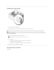
... any installed PCI or PCI Express cards (see Removing the Chassis Support Bracket). Disconnect the DC power cables from the electrical outlet before removing the cover. Remove the screws that attach the power supply to Contents Page Power Supply Dell™ Vostro™ 420/220/220s Service Manual Removing the Power Supply Replacing the...
... any installed PCI or PCI Express cards (see Removing the Chassis Support Bracket). Disconnect the DC power cables from the electrical outlet before removing the cover. Remove the screws that attach the power supply to Contents Page Power Supply Dell™ Vostro™ 420/220/220s Service Manual Removing the Power Supply Replacing the...
Service Manual
Page 38
...: a. b. c. Follow the procedure in After Working on Your Computer. DC Power Supply Connectors Vostro 420 NOTE: Double-check all screws may cause electrical shock as you insert them into the routing clips (if present). Replace the chassis support bracket (see Installing a PCI or PCI Express Card). Reconnect the DC power cables to prevent...
...: a. b. c. Follow the procedure in After Working on Your Computer. DC Power Supply Connectors Vostro 420 NOTE: Double-check all screws may cause electrical shock as you insert them into the routing clips (if present). Replace the chassis support bracket (see Installing a PCI or PCI Express Card). Reconnect the DC power cables to prevent...

Service Manual
Page 42
... memory modules from the system board (see Removing the Computer Cover). 3. Disconnect the chassis fan cable from the system board. 8. Back to Contents Page System Board Dell™ Vostro™ 420/220/220s Service Manual Remove the System Board Replacing a System Board CAUTION: Before working... inside your computer, read the safety information that secure the system board to the computer chassis. Remove all expansion cards (see...
... memory modules from the system board (see Removing the Computer Cover). 3. Disconnect the chassis fan cable from the system board. 8. Back to Contents Page System Board Dell™ Vostro™ 420/220/220s Service Manual Remove the System Board Replacing a System Board CAUTION: Before working... inside your computer, read the safety information that secure the system board to the computer chassis. Remove all expansion cards (see...


