
Service Manual
Page 1
... better use of your computer. Bluetooth is a registered trademark owned by Dell under license. Dell™ Vostro™ 420/220/220s Service Manual Troubleshooting Working on Your Computer Computer Cover Bezel Chassis Support Bracket PCI and PCI Express Cards Drives I/O Panel Fan Processor Heat Sink/Fan Assembly Memory Module(s) Power Supply Coin-Cell Battery System Board Processor...
... better use of your computer. Bluetooth is a registered trademark owned by Dell under license. Dell™ Vostro™ 420/220/220s Service Manual Troubleshooting Working on Your Computer Computer Cover Bezel Chassis Support Bracket PCI and PCI Express Cards Drives I/O Panel Fan Processor Heat Sink/Fan Assembly Memory Module(s) Power Supply Coin-Cell Battery System Board Processor...

Service Manual
Page 28
... Before Working on Your Computer. 2. Back to the chassis. 5. the illustrations provided are for the Vostro 420, Vostro 220, and Vostro 220s computers; Follow the procedures in place, remove the screw(s) that secure(s) the fan to Contents Page Fan Dell™ Vostro™ 420/220/220s Service Manual Removing the Chassis Fan Replacing the Chassis Fan CAUTION: Before working inside your computer, read the...
... Before Working on Your Computer. 2. Back to the chassis. 5. the illustrations provided are for the Vostro 420, Vostro 220, and Vostro 220s computers; Follow the procedures in place, remove the screw(s) that secure(s) the fan to Contents Page Fan Dell™ Vostro™ 420/220/220s Service Manual Removing the Chassis Fan Replacing the Chassis Fan CAUTION: Before working inside your computer, read the...

Service Manual
Page 29
1 chassis fan 3 screws (4) Vostro 220s 2 system board power connector 1 system board power connector 3 screw 2 chassis fan Replacing the Chassis Fan 1. c. For the Vostro 220s: a. b. Proceed to step 3. Press the fan into the chassis such that the screw hole in the fan is offset and slightly forward of the computer until it toward the back of the screw hole in the fan mount on the chassis. Lower the fan into the side of the chassis, and then slide it sets against the stops.
1 chassis fan 3 screws (4) Vostro 220s 2 system board power connector 1 system board power connector 3 screw 2 chassis fan Replacing the Chassis Fan 1. c. For the Vostro 220s: a. b. Proceed to step 3. Press the fan into the chassis such that the screw hole in the fan is offset and slightly forward of the computer until it toward the back of the screw hole in the fan mount on the chassis. Lower the fan into the side of the chassis, and then slide it sets against the stops.

Service Manual
Page 30
Attach the fan cable to Contents Page Follow the procedure in place, align the screw hole(s) and install the screw(s) that secure the fan to the chassis. 3. While holding the chassis fan in After Working on Your Computer. 2. Back to the system board (see System Board Components). 4.
Attach the fan cable to Contents Page Follow the procedure in place, align the screw hole(s) and install the screw(s) that secure the fan to the chassis. 3. While holding the chassis fan in After Working on Your Computer. 2. Back to the system board (see System Board Components). 4.

Service Manual
Page 42
...gain access to the PWR1 connector on Your Computer. 2. Disconnect the DC power cables from the system board. 10. c. Disconnect the chassis fan cable from the system board. 8. Disconnect all expansion cards (see Removing a PCI or PCI Express Card). Remove the screws that ...Back to Contents Page System Board Dell™ Vostro™ 420/220/220s Service Manual Remove the System Board Replacing a System Board CAUTION: Before working inside your computer, read the safety information that secure the system board to the computer chassis. For additional safety best practices information...
...gain access to the PWR1 connector on Your Computer. 2. Disconnect the DC power cables from the system board. 10. c. Disconnect the chassis fan cable from the system board. 8. Disconnect all expansion cards (see Removing a PCI or PCI Express Card). Remove the screws that ...Back to Contents Page System Board Dell™ Vostro™ 420/220/220s Service Manual Remove the System Board Replacing a System Board CAUTION: Before working inside your computer, read the safety information that secure the system board to the computer chassis. For additional safety best practices information...

Service Manual
Page 43
...new system board: a. CAUTION: Failure to replace and tighten all screws properly may not provide adequate grounding of the chassis. 2. b. Connect the chassis fan cable to the chassis. Replace the screws that the back panel connectors are properly aligned in the openings on the back of the system board... and result in the chassis, ensuring that secure the system board to the system board. 4. Install the memory modules ...
...new system board: a. CAUTION: Failure to replace and tighten all screws properly may not provide adequate grounding of the chassis. 2. b. Connect the chassis fan cable to the chassis. Replace the screws that the back panel connectors are properly aligned in the openings on the back of the system board... and result in the chassis, ensuring that secure the system board to the system board. 4. Install the memory modules ...
Service Manual
Page 44
... drive back fully into the drive bay. 11. Connect any additional cables to ensure that they are secure. Install all cable connections throughout the computer chassis to the system board as required. 9. Follow the procedure in After Working on the system board. 12. Install the processor heat sink...
... drive back fully into the drive bay. 11. Connect any additional cables to ensure that they are secure. Install all cable connections throughout the computer chassis to the system board as required. 9. Follow the procedure in After Working on the system board. 12. Install the processor heat sink...
Service Manual
Page 67
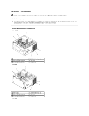
Inside View of Your Computer Vostro™ 420 1 power supply 3 media card reader (optional) 5 3.5-inch hard drive bays (4) Vostro 220 2 5.25-inch drive bays (3) 4 I/O panel 6 chassis fan 1 power supply 3 media card reader (optional) 5 3.5-inch hard drive bays (2) Vostro 220s 2 5.25-inch drive bays (2) 4 I/O panel 6 chassis fan Turning Off Your Computer NOTICE: To avoid losing data, save and close all...
Inside View of Your Computer Vostro™ 420 1 power supply 3 media card reader (optional) 5 3.5-inch hard drive bays (4) Vostro 220 2 5.25-inch drive bays (3) 4 I/O panel 6 chassis fan 1 power supply 3 media card reader (optional) 5 3.5-inch hard drive bays (2) Vostro 220s 2 5.25-inch drive bays (2) 4 I/O panel 6 chassis fan Turning Off Your Computer NOTICE: To avoid losing data, save and close all...

Service Manual
Page 69
... USB ports (2) ports 28 USB ports (2) and ESATA connector 29 chassis fan connector 30 Display Port 31 video (VGA) and parallel ports 32 PS/2 mouse and keyboard connectors Vostro 220 1 power connector (PWR2) 2 processor heat sink/fan assembly power 4 main power connector (PWR1) 5 serial ATA drive... board CMOS) connector 16 PCI connector (PCI1) 17 PCI connector (PCI2) 19 PCI Express x1 20 audio connectors connector (PCIE_X1) 22 chassis fan power 23 USB ports (2) 25 PS/2 mouse and keyboard connectors 3 memory module connectors (2) 6 serial ATA drive connector (SATA1) 9 battery...
... USB ports (2) ports 28 USB ports (2) and ESATA connector 29 chassis fan connector 30 Display Port 31 video (VGA) and parallel ports 32 PS/2 mouse and keyboard connectors Vostro 220 1 power connector (PWR2) 2 processor heat sink/fan assembly power 4 main power connector (PWR1) 5 serial ATA drive... board CMOS) connector 16 PCI connector (PCI1) 17 PCI connector (PCI2) 19 PCI Express x1 20 audio connectors connector (PCIE_X1) 22 chassis fan power 23 USB ports (2) 25 PS/2 mouse and keyboard connectors 3 memory module connectors (2) 6 serial ATA drive connector (SATA1) 9 battery...

Service Manual
Page 70
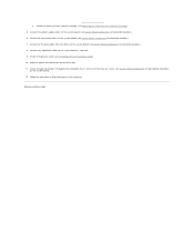
...14 USB3 system board CMOS) connector 16 PCI connector (PCI1) 17 PCI connector (PCI2) 19 PCI Express x1 20 audio connectors connector (PCIE_X1) 22 chassis fan power 23 USB ports (2) 25 PS/2 mouse and keyboard connectors 3 memory module connectors (2) 6 serial ATA drive connector (SATA1) 9 battery socket 12... you connect any external devices, cards, cables, and so on, before turning on your Setup and Quick Reference Guide for help running the Dell Diagnostics. NOTICE: To connect a network cable, first plug the cable into the network device and then plug it into the computer. 3. See...
...14 USB3 system board CMOS) connector 16 PCI connector (PCI1) 17 PCI connector (PCI2) 19 PCI Express x1 20 audio connectors connector (PCIE_X1) 22 chassis fan power 23 USB ports (2) 25 PS/2 mouse and keyboard connectors 3 memory module connectors (2) 6 serial ATA drive connector (SATA1) 9 battery socket 12... you connect any external devices, cards, cables, and so on, before turning on your Setup and Quick Reference Guide for help running the Dell Diagnostics. NOTICE: To connect a network cable, first plug the cable into the network device and then plug it into the computer. 3. See...


