Setup and Quick Reference Guide
Page 31
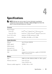
...connectors Memory modules supported DDR2 800 MHz SDRAM (DDR2 667 MHz capable) Vostro 420: four Vostro 220/220s: two 512 MB, 1 GB, or 2 GB Specifications 31 Processor Processor types: Vostro 420: Vostro 220, 220s: Level 2 (L2) cache Front side bus Intel® Core™...;2 Quad, Core™2 Duo processors Intel Core™2 Duo, Celeron®, Pentium® processors minimum 512 KB, maximum 12 MB 800 MHz, 1066 MHz, or 1333 MHz System Information Chipset RAID support DMA channels Interrupt levels BIOS...
...connectors Memory modules supported DDR2 800 MHz SDRAM (DDR2 667 MHz capable) Vostro 420: four Vostro 220/220s: two 512 MB, 1 GB, or 2 GB Specifications 31 Processor Processor types: Vostro 420: Vostro 220, 220s: Level 2 (L2) cache Front side bus Intel® Core™...;2 Quad, Core™2 Duo processors Intel Core™2 Duo, Celeron®, Pentium® processors minimum 512 KB, maximum 12 MB 800 MHz, 1066 MHz, or 1333 MHz System Information Chipset RAID support DMA channels Interrupt levels BIOS...

Service Manual
Page 45
Back to Contents Page System Setup Program Dell™ Vostro™ 420/220/220s Service Manual Overview Entering the System Setup Program System Setup Program Screens System Setup Program Options Boot Sequence Clearing Forgotten Passwords Clearing CMOS Settings BIOS Overview Use the system setup program as follows: l To change the .... Turn on the screen is divided into three areas: the options list, active options field, and key functions. When the blue DELL™ logo is highlighted, the Use the right and left side of hard drive installed Before you use the system setup program, it...
Back to Contents Page System Setup Program Dell™ Vostro™ 420/220/220s Service Manual Overview Entering the System Setup Program System Setup Program Screens System Setup Program Options Boot Sequence Clearing Forgotten Passwords Clearing CMOS Settings BIOS Overview Use the system setup program as follows: l To change the .... Turn on the screen is divided into three areas: the options list, active options field, and key functions. When the blue DELL™ logo is highlighted, the Use the right and left side of hard drive installed Before you use the system setup program, it...

Service Manual
Page 51
...on the keyboard, move the mouse, or press the power button to Contents Page Troubleshooting Dell™ Vostro™ 420/220/220s Service Manual Tools Dell Diagnostics Solving Problems Dell Technical Update Service Dell Support Utility Tools Power Lights CAUTION: Before working by testing it with your location, ... is set to the system board (see Beep Codes. Possible system board failure. Code (repetitive short beeps) 1 Description BIOS checksum failure. For additional safety best practices information, see the Regulatory Compliance Homepage at your computer. l If the power ...
...on the keyboard, move the mouse, or press the power button to Contents Page Troubleshooting Dell™ Vostro™ 420/220/220s Service Manual Tools Dell Diagnostics Solving Problems Dell Technical Update Service Dell Support Utility Tools Power Lights CAUTION: Before working by testing it with your location, ... is set to the system board (see Beep Codes. Possible system board failure. Code (repetitive short beeps) 1 Description BIOS checksum failure. For additional safety best practices information, see the Regulatory Compliance Homepage at your computer. l If the power ...

Service Manual
Page 66
... that shipped with your computer. Back to Contents Page Working on Your Computer Dell™ Vostro™ 420/220/220s Service Manual Recommended Tools Before Working on Your Computer Inside View of Your Computer... System Board Components After Working on Your Computer This document provides procedures for removing and installing the components in this document may require the following tools: l Small flat-blade screwdriver l Phillips screwdriver l Small plastic scribe l Flash BIOS...
... that shipped with your computer. Back to Contents Page Working on Your Computer Dell™ Vostro™ 420/220/220s Service Manual Recommended Tools Before Working on Your Computer Inside View of Your Computer... System Board Components After Working on Your Computer This document provides procedures for removing and installing the components in this document may require the following tools: l Small flat-blade screwdriver l Phillips screwdriver l Small plastic scribe l Flash BIOS...


