
Service Manual
Page 3
... Battery...31 Lithium-ion battery precautions...31 Removing the battery...32 Installing the battery...32 Contents 3 Contents 1 Working on your computer...6 Safety instructions...6 Turning off your computer...7 2 Technology and components...8 DDR4...8 HDMI 1.4...9 USB features...10 Intel Optane memory...11 Enabling Intel Optane memory...12 Disabling Intel Optane memory...12 3 Removing and installing components 13 Recommended tools...13 Screw list...13 Micro Secure Digital Card...14 Removing the Micro Secure Digital card...14 Installing...
... Battery...31 Lithium-ion battery precautions...31 Removing the battery...32 Installing the battery...32 Contents 3 Contents 1 Working on your computer...6 Safety instructions...6 Turning off your computer...7 2 Technology and components...8 DDR4...8 HDMI 1.4...9 USB features...10 Intel Optane memory...11 Enabling Intel Optane memory...12 Disabling Intel Optane memory...12 3 Removing and installing components 13 Recommended tools...13 Screw list...13 Micro Secure Digital Card...14 Removing the Micro Secure Digital card...14 Installing...
Service Manual
Page 6
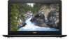
... cable itself. CAUTION: When you finish working inside the computer, replace all power sources before connecting to avoid bending any connector pins. As you are correctly oriented and aligned. Turning off your computer if you pull connectors apart, keep them evenly aligned to the power source. Windows 10 About this task NOTE: Disconnect all covers, panels, and screws before opening the computer cover...
... cable itself. CAUTION: When you finish working inside the computer, replace all power sources before connecting to avoid bending any connector pins. As you are correctly oriented and aligned. Turning off your computer if you pull connectors apart, keep them evenly aligned to the power source. Windows 10 About this task NOTE: Disconnect all covers, panels, and screws before opening the computer cover...

Service Manual
Page 7
... task To avoid damaging your computer, perform the following steps before turning on your operating system, press and hold the power button while the computer is flat and clean to ground the system board. If required, verify that you connect any external devices, cards, and cables before you complete any telephone or network cables to their electrical outlets. 6. Before working inside the computer.
... task To avoid damaging your computer, perform the following steps before turning on your operating system, press and hold the power button while the computer is flat and clean to ground the system board. If required, verify that you connect any external devices, cards, and cables before you complete any telephone or network cables to their electrical outlets. 6. Before working inside the computer.
Service Manual
Page 9
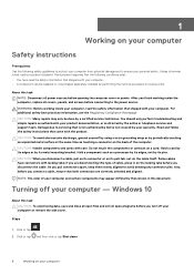
.... HDMI supports standard, enhanced, or high-definition video, plus multichannel digital audio on the system display the new ON-FLASH-FLASH or ON-FLASH-ON failure code. Adds high-speed networking to an HDMI link, allowing users to optimize picture settings based on . Allows an HDMI-connected TV with a built-in tuner to send audio data "upstream" to multichannel surround sound • HDMI combines video and multichannel audio into a single cable, eliminating...
.... HDMI supports standard, enhanced, or high-definition video, plus multichannel digital audio on the system display the new ON-FLASH-FLASH or ON-FLASH-ON failure code. Adds high-speed networking to an HDMI link, allowing users to optimize picture settings based on . Allows an HDMI-connected TV with a built-in tuner to send audio data "upstream" to multichannel surround sound • HDMI combines video and multichannel audio into a single cable, eliminating...

Service Manual
Page 10
... to better accommodate power-hungry devices • New power management features • Full-duplex data transfers and support for differential data); • HDMI supports communication between host computers and peripheral devices like mice, keyboards, external drivers, and printers. Speed Currently, there are Super-Speed, Hi-Speed and FullSpeed. USB 3.0/USB 3.1 Gen 1 adds four more speed grows by the latest USB 3.0/USB 3.1 Gen 1 specification. The USB 3.0/USB 3.1 Gen 1 finally has...
... to better accommodate power-hungry devices • New power management features • Full-duplex data transfers and support for differential data); • HDMI supports communication between host computers and peripheral devices like mice, keyboards, external drivers, and printers. Speed Currently, there are Super-Speed, Hi-Speed and FullSpeed. USB 3.0/USB 3.1 Gen 1 adds four more speed grows by the latest USB 3.0/USB 3.1 Gen 1 specification. The USB 3.0/USB 3.1 Gen 1 finally has...

Service Manual
Page 11
... connections and thus new cables to take advantage of the higher speed capability of 400MB/s with the four USB 2.0 contacts in contrast to previous versions of the available SuperSpeed USB 3.0/USB 3.1 Gen 1 products: • External Desktop USB 3.0/USB 3.1 Gen 1 Hard Drives • Portable USB 3.0/USB 3.1 Gen 1 Hard Drives • USB 3.0/USB 3.1 Gen 1 Drive Docks & Adapters • USB 3.0/USB 3.1 Gen 1 Flash Drives & Readers • USB 3.0/USB 3.1 Gen 1 Solid-state Drives • USB 3.0/USB 3.1 Gen 1 RAIDs • Optical Media Drives • Multimedia Devices • Networking...
... connections and thus new cables to take advantage of the higher speed capability of 400MB/s with the four USB 2.0 contacts in contrast to previous versions of the available SuperSpeed USB 3.0/USB 3.1 Gen 1 products: • External Desktop USB 3.0/USB 3.1 Gen 1 Hard Drives • Portable USB 3.0/USB 3.1 Gen 1 Hard Drives • USB 3.0/USB 3.1 Gen 1 Drive Docks & Adapters • USB 3.0/USB 3.1 Gen 1 Flash Drives & Readers • USB 3.0/USB 3.1 Gen 1 Solid-state Drives • USB 3.0/USB 3.1 Gen 1 RAIDs • Optical Media Drives • Multimedia Devices • Networking...

Service Manual
Page 22
... procedure in before working inside your computer Memory modules Removing the memory module Prerequisites 1. Remove the optical drive assembly 4. Next steps 1. Follow the procedure in after working inside your computer 2. Remove the SD memory card 3. Disconnect the battery cable from the memory module slot [2]. Steps 1. Align the notch on the memory module with the tab on the system board. Replace the optical drive assembly 2. Remove the memory module from the connector on the memory-module slot. 2. Installing the memory module Steps 1.
... procedure in before working inside your computer Memory modules Removing the memory module Prerequisites 1. Remove the optical drive assembly 4. Next steps 1. Follow the procedure in after working inside your computer 2. Remove the SD memory card 3. Disconnect the battery cable from the memory module slot [2]. Steps 1. Align the notch on the memory module with the tab on the system board. Replace the optical drive assembly 2. Remove the memory module from the connector on the memory-module slot. 2. Installing the memory module Steps 1.

Service Manual
Page 23
Connect the battery cable to the system board [1]. 2. Replace the base cover 3. Follow the procedure in after working inside your computer 2. Steps 1. Slide and remove the WLAN card bracket that secures the WLAN card bracket to the connector on the system board. Lift the WLAN card away from the connectors on the WLAN card [3]. 4. Remove the SD memory card 3. Remove the optical drive assembly 4. Disconnect the battery cable from the connector...
Connect the battery cable to the system board [1]. 2. Replace the base cover 3. Follow the procedure in after working inside your computer 2. Steps 1. Slide and remove the WLAN card bracket that secures the WLAN card bracket to the connector on the system board. Lift the WLAN card away from the connectors on the WLAN card [3]. 4. Remove the SD memory card 3. Remove the optical drive assembly 4. Disconnect the battery cable from the connector...

Service Manual
Page 85
... the preceding steps, you are left with fingerprint reader 20. Remove the hard drive assembly 12. Remove the battery 6. Remove the IO board 16. Remove the power button with the palmrest and keyboard assembly. NOTE: The system board can be removed and installed together with the heatsink still attached. Remove the SD memory card 3. Remove the base cover 5. Remove the power adapter port 22. Remove the display assembly 18. Remove the speakers 10. Follow the procedure in...
... the preceding steps, you are left with fingerprint reader 20. Remove the hard drive assembly 12. Remove the battery 6. Remove the IO board 16. Remove the power button with the palmrest and keyboard assembly. NOTE: The system board can be removed and installed together with the heatsink still attached. Remove the SD memory card 3. Remove the base cover 5. Remove the power adapter port 22. Remove the display assembly 18. Remove the speakers 10. Follow the procedure in...
Service Manual
Page 87
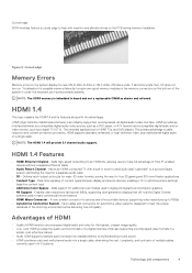
... error code and validation number and contact Dell. Off • Power adapter is connected and the battery is fully charged. • Computer is running on a specific device, press Esc and click Yes to the page listing. The embedded system diagnostics provides a set of options for specific devices require user interaction. To run a diagnostic test on battery and the battery has less than 5 percent charge. • Computer is displayed. 5. The power and battery-status light blinks...
... error code and validation number and contact Dell. Off • Power adapter is connected and the battery is fully charged. • Computer is running on a specific device, press Esc and click Yes to the page listing. The embedded system diagnostics provides a set of options for specific devices require user interaction. To run a diagnostic test on battery and the battery has less than 5 percent charge. • Computer is displayed. 5. The power and battery-status light blinks...
Service Manual
Page 88
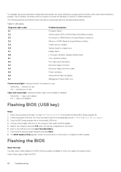
... One Time Boot Menu. 7. Boot to download the latest BIOS setup program file. 2. Replace system board Coin-cell battery failure PCI, video card/chip failure Recovery image not found Recovery image found but invalid Power-rail failure System BIOS Flash incomplete Management Engine (ME) error Camera status light: Indicates whether the camera is enabled or disabled. • Solid white - Caps Lock status light: Indicates whether Caps Lock is in "Flashing the BIOS" to the USB drive from step 1 to step 7 in use. •...
... One Time Boot Menu. 7. Boot to download the latest BIOS setup program file. 2. Replace system board Coin-cell battery failure PCI, video card/chip failure Recovery image not found Recovery image found but invalid Power-rail failure System BIOS Flash incomplete Management Engine (ME) error Camera status light: Indicates whether the camera is enabled or disabled. • Solid white - Caps Lock status light: Indicates whether Caps Lock is in "Flashing the BIOS" to the USB drive from step 1 to step 7 in use. •...
Service Manual
Page 89
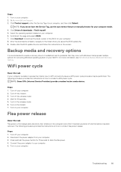
... you do not have the Service Tag, use the auto-detect feature or manually browse for 30 seconds. 5. Troubleshooting 89 Steps 1. see Dell Windows Backup Media and Recovery Options. WiFi power cycle About this task Flea power is recommended to create a recovery drive to www.dell.com/support. 3. Turn on the computer even after it myself. 5. Disconnect the power adapter from your computer. 2. Go to troubleshoot and fix problems that remains on the wireless router. 6.
... you do not have the Service Tag, use the auto-detect feature or manually browse for 30 seconds. 5. Troubleshooting 89 Steps 1. see Dell Windows Backup Media and Recovery Options. WiFi power cycle About this task Flea power is recommended to create a recovery drive to www.dell.com/support. 3. Turn on the computer even after it myself. 5. Disconnect the power adapter from your computer. 2. Go to troubleshoot and fix problems that remains on the wireless router. 6.

Setup and specifications guide
Page 7
... Windows using the USB recovery drive, see the Troubleshooting section of your computer. 2 In Windows search, type Recovery. 3 In the search results, click Create a recovery drive. Steps 1 Connect the USB flash drive to your product's Service Manual at www.dell.com/support/manuals. 2 Create a USB recovery drive for Windows 7 Create a USB recovery drive for Windows Create a recovery drive to complete. The Recovery Drive window is displayed. 5 Select Back up to an hour to troubleshoot and fix problems that all data in the USB flash drive will be deleted. 7 Click Create...
... Windows using the USB recovery drive, see the Troubleshooting section of your computer. 2 In Windows search, type Recovery. 3 In the search results, click Create a recovery drive. Steps 1 Connect the USB flash drive to your product's Service Manual at www.dell.com/support/manuals. 2 Create a USB recovery drive for Windows 7 Create a USB recovery drive for Windows Create a recovery drive to complete. The Recovery Drive window is displayed. 5 Select Back up to an hour to troubleshoot and fix problems that all data in the USB flash drive will be deleted. 7 Click Create...

Setup and specifications guide
Page 12
... + F8 Fn + F9 Fn + F11 Fn + F12 Fn + PrtScr Fn + Ctrl Description Toggle Fn-key lock Mute audio Decrease volume Increase volume Play previous Play / Pause Play next Switch to external display Search Decrease brightness Increase brightness Turn on the keyboard language configuration. 4 Keyboard shortcuts NOTE: Keyboard characters may differ depending on /off wireless Open application menu 12 Keyboard shortcuts Table 2. Keys used for shortcuts remain the same across all language...
... + F8 Fn + F9 Fn + F11 Fn + F12 Fn + PrtScr Fn + Ctrl Description Toggle Fn-key lock Mute audio Decrease volume Increase volume Play previous Play / Pause Play next Switch to external display Search Decrease brightness Increase brightness Turn on the keyboard language configuration. 4 Keyboard shortcuts NOTE: Keyboard characters may differ depending on /off wireless Open application menu 12 Keyboard shortcuts Table 2. Keys used for shortcuts remain the same across all language...
Setup and specifications guide
Page 23
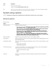
... default, no option is installed. Keys Tab Navigation Moves to set the date and time settings. Displays the battery status health and whether the AC adapter is selected. • Enable Legacy Option ROMs • Enable Attempt Legacy Boot This option controls whether or not the system will prompt the user to enter the Admin password when booting a UEFI boot path from the devices specified in this list. Allows you to specify the order in...
... default, no option is installed. Keys Tab Navigation Moves to set the date and time settings. Displays the battery status health and whether the AC adapter is selected. • Enable Legacy Option ROMs • Enable Attempt Legacy Boot This option controls whether or not the system will prompt the user to enter the Admin password when booting a UEFI boot path from the devices specified in this list. Allows you to specify the order in...
Setup and specifications guide
Page 24
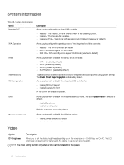
...; Enable USB Boot Support • Enable External USB Port All the options are enabled by default) Smart Reporting USB Configuration This field controls whether hard drive errors for integrated drives are reported during system startup. The LCD brightness is installed into the system. 24 System setup It can be set the display brightness depending up on the power source-On Battery and On AC. System information Table 26. Audio Allows you to enable or disable the following devices: • Enable Camera (enabled by default. System Configuration Option Integrated...
...; Enable USB Boot Support • Enable External USB Port All the options are enabled by default) Smart Reporting USB Configuration This field controls whether hard drive errors for integrated drives are reported during system startup. The LCD brightness is installed into the system. 24 System setup It can be set the display brightness depending up on the power source-On Battery and On AC. System information Table 26. Audio Allows you to enable or disable the following devices: • Enable Camera (enabled by default. System Configuration Option Integrated...
Setup and specifications guide
Page 25
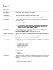
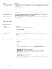
... prompt for Clear Commands • Attestation Enable (default) • Key Storage Enable (default) • SHA-256 (default) Choose any module bay HDDs that may be present. Allows you enable or disable strong passwords for asset management. • Deactivate • Disable • Activate - This option lets you to control whether the Trusted Platform Module (TPM) is set . Disabling this system allows BIOS updates via UEFI capsule update packages. Security Option Admin Password System Password Strong Password Password Configuration Password Bypass Password Change Description...
... prompt for Clear Commands • Attestation Enable (default) • Key Storage Enable (default) • SHA-256 (default) Choose any module bay HDDs that may be present. Allows you enable or disable strong passwords for asset management. • Deactivate • Disable • Activate - This option lets you to control whether the Trusted Platform Module (TPM) is set . Disabling this system allows BIOS updates via UEFI capsule update packages. Security Option Admin Password System Password Strong Password Password Configuration Password Bypass Password Change Description...
Setup and specifications guide
Page 26
... If you disable the Custom Mode, all the changes made will be changed. This option is set by default. Allows you to a user-selected file • Replace from File- This option is disabled by default. The options are able to enter Option ROM configuration screen via hotkeys during boot. • Enabled (default) • Disabled • One Time Enable Allows you to the current database from entering Setup when Admin password is not set by default. Adds a key to enable or disable additional...
... If you disable the Custom Mode, all the changes made will be changed. This option is set by default. Allows you to a user-selected file • Replace from File- This option is disabled by default. The options are able to enter Option ROM configuration screen via hotkeys during boot. • Enabled (default) • Disabled • One Time Enable Allows you to the current database from entering Setup when Admin password is not set by default. Adds a key to enable or disable additional...

Setup and specifications guide
Page 28
... % (enabled by a LAN signal. • Disabled • WLAN Default setting: Disabled Peak Shift This option enables you to minimize the AC power consumption during Standby, the system setup removes power from turning on automatically when an AC adapter is connected. After you enable this option, your system runs only in the processor. • Disabled • Enabled-Default Power management Option AC Behavior Description Allows you to maximize the battery health. Enable Advanced Battery Charge Mode- If the AC power adapter...
... % (enabled by a LAN signal. • Disabled • WLAN Default setting: Disabled Peak Shift This option enables you to minimize the AC power consumption during Standby, the system setup removes power from turning on automatically when an AC adapter is connected. After you enable this option, your system runs only in the processor. • Disabled • Enabled-Default Power management Option AC Behavior Description Allows you to maximize the battery health. Enable Advanced Battery Charge Mode- If the AC power adapter...

Setup and specifications guide
Page 29
... BIOS POST Time Allows you to create an extra preboot delay. POST behavior Option Adapter Warnings Description Allows you to select the charging mode for all the batteries. Enable Network. If you cannot toggle dynamically the primary behavior of F1-F12, between their standard and secondary functions. To enable this option, you disable this option, disable the Advanced Battery Charge Configuration option. The options are : • Fn Lock-enabled by default • Lock Mode Disable/Standard-enabled...
... BIOS POST Time Allows you to create an extra preboot delay. POST behavior Option Adapter Warnings Description Allows you to select the charging mode for all the batteries. Enable Network. If you cannot toggle dynamically the primary behavior of F1-F12, between their standard and secondary functions. To enable this option, you disable this option, disable the Advanced Battery Charge Configuration option. The options are : • Fn Lock-enabled by default • Lock Mode Disable/Standard-enabled...


