
Setup and Features Information Tech Sheet
Page 2
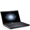
... 1 cooling vent 2 AC adapter connector 3 USB 2.0 connector 4 network connector 5 optical drive/bay 6 ExpressCard connector 1 6 5 4 3 2 WARNING: Do not block,... tables in the cooling vents. FILE LOCATION: C:\Documents and Settings\kandasamy_m\Desktop\Winery_A01\Info Dev Vostro 3300 - Work with your illustrator to accumulate in this section are placeholders only. Restricting the .... Do not store your platform. Fan noise is running. Use the following template for your Dell computer in a low-airflow environment, such as a closed briefcase, while it is normal and does...
... 1 cooling vent 2 AC adapter connector 3 USB 2.0 connector 4 network connector 5 optical drive/bay 6 ExpressCard connector 1 6 5 4 3 2 WARNING: Do not block,... tables in the cooling vents. FILE LOCATION: C:\Documents and Settings\kandasamy_m\Desktop\Winery_A01\Info Dev Vostro 3300 - Work with your illustrator to accumulate in this section are placeholders only. Restricting the .... Do not store your platform. Fan noise is running. Use the following template for your Dell computer in a low-airflow environment, such as a closed briefcase, while it is normal and does...
Setup and Features Information Tech Sheet
Page 3
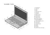
Vostro 3400/3500 - Front View 21 1 2 3 4 20 19 18 17 16 15 14 10 11 12 13 5 6 7 8 9 FILE LOCATION: C:\Documents and Settings\kandasamy_m\Desktop\Winery_A01\Info Dev 1 microphones (2) 2 camera light 3 camera 4 display 5 volume control buttons 6 power button 7 right speaker 8 network connector 9 USB 2.0 connector 10 optical drive/bay 11 fingerprint reader 12 ExpressCard connector 13 8-in...
Vostro 3400/3500 - Front View 21 1 2 3 4 20 19 18 17 16 15 14 10 11 12 13 5 6 7 8 9 FILE LOCATION: C:\Documents and Settings\kandasamy_m\Desktop\Winery_A01\Info Dev 1 microphones (2) 2 camera light 3 camera 4 display 5 volume control buttons 6 power button 7 right speaker 8 network connector 9 USB 2.0 connector 10 optical drive/bay 11 fingerprint reader 12 ExpressCard connector 13 8-in...
Setup and Features Information Tech Sheet
Page 5
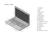
...: C:\Documents and Settings\kandasamy_m\Desktop\Winery_A01\Info Dev 1 microphones (2) 2 camera light 3 camera 4 display 5 volume control lights 6 power button 7 right speaker 8 network connector 9 USB 2.0 connectors (2) 10 optical drive/bay 11 fingerprint reader 12 IEEE 1394 connector 13 ExpressCard slot 14 8-in-1 Secure Digital (SD) memory card reader 15 power and battery status lights...
...: C:\Documents and Settings\kandasamy_m\Desktop\Winery_A01\Info Dev 1 microphones (2) 2 camera light 3 camera 4 display 5 volume control lights 6 power button 7 right speaker 8 network connector 9 USB 2.0 connectors (2) 10 optical drive/bay 11 fingerprint reader 12 IEEE 1394 connector 13 ExpressCard slot 14 8-in-1 Secure Digital (SD) memory card reader 15 power and battery status lights...
Setup and Features Information Tech Sheet
Page 10
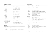
...4-cell Physical (continued) Width 325.00 mm (12.79 inches) Weight 1.80 kg (3.96 lb) with 6-cell and media drives. NOTE: Optical drive includes the optical drive, bracket, and bezel. Vostro 3400 Depth 242.2 mm (9.53 inches) Height 21.90 mm-29.50 mm (0.86 inch-1.16 inches) with 4-cell/6-cell ... area Width 375.00 mm (14.76 inches) Weight 2.30 kg (5.07 lb) with 4-cell and media drives. FILE LOCATION: C:\Documents and Settings\kandasamy_m\Desktop\Winery_A01\Info Dev Vostro 3500 Depth 250.0 mm (9.84 inches) Height 22.90 mm-31.90 mm (0.90 inches-1.25 inches) with 6-cell...
...4-cell Physical (continued) Width 325.00 mm (12.79 inches) Weight 1.80 kg (3.96 lb) with 6-cell and media drives. NOTE: Optical drive includes the optical drive, bracket, and bezel. Vostro 3400 Depth 242.2 mm (9.53 inches) Height 21.90 mm-29.50 mm (0.86 inch-1.16 inches) with 4-cell/6-cell ... area Width 375.00 mm (14.76 inches) Weight 2.30 kg (5.07 lb) with 4-cell and media drives. FILE LOCATION: C:\Documents and Settings\kandasamy_m\Desktop\Winery_A01\Info Dev Vostro 3500 Depth 250.0 mm (9.84 inches) Height 22.90 mm-31.90 mm (0.90 inches-1.25 inches) with 6-cell...
Service Manual
Page 2
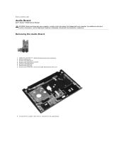
Remove the battery. 3. Remove the screw that secures the audio board to Contents Page Audio Board Dell™ Vostro™ 3500 Service Manual WARNING: Before working inside your computer, read the safety information that shipped with your computer. ...Homepage at www.dell.com/regulatory_compliance. Remove the base cover. 4. Remove the keyboard. 7. Follow the procedures in Before Working Inside Your Computer. 2. Remove the palm rest. 8. Disconnect the speaker cable from its connector on the audio board. Remove the optical drive. 6. Remove the hard drive assembly. 5. Removing...
Remove the battery. 3. Remove the screw that secures the audio board to Contents Page Audio Board Dell™ Vostro™ 3500 Service Manual WARNING: Before working inside your computer, read the safety information that shipped with your computer. ...Homepage at www.dell.com/regulatory_compliance. Remove the base cover. 4. Remove the keyboard. 7. Follow the procedures in Before Working Inside Your Computer. 2. Remove the palm rest. 8. Disconnect the speaker cable from its connector on the audio board. Remove the optical drive. 6. Remove the hard drive assembly. 5. Removing...
Service Manual
Page 12
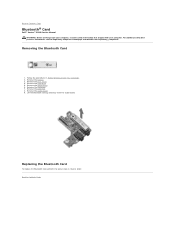
... To replace the Bluetooth card, perform the above steps in Before Working Inside Your Computer. 2. Remove the optical drive. 6. Follow the procedures in reverse order. Back to Contents Page Bluetooth® Card Dell™ Vostro™ 3500 Service Manual WARNING: Before working inside your computer, read the safety information that shipped with your computer. Back...
... To replace the Bluetooth card, perform the above steps in Before Working Inside Your Computer. 2. Remove the optical drive. 6. Follow the procedures in reverse order. Back to Contents Page Bluetooth® Card Dell™ Vostro™ 3500 Service Manual WARNING: Before working inside your computer, read the safety information that shipped with your computer. Back...
Service Manual
Page 13
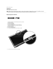
Back to Contents Page Camera Dell™ Vostro™ 3500 Service Manual WARNING: Before working inside your computer, read the safety information that shipped with your computer. Remove the battery. 3. Remove the .... 13. For additional safety best practices information, see the Regulatory Compliance Homepage at www.dell.com/regulatory_compliance. Follow the procedures in Before Working Inside Your Computer. 2. Remove the display bezel. 12. Remove the hard drive. 5. Remove the wireless wide area network (WWAN) card. 8. Remove the optical drive. 6. Remove the base cover. 4.
Back to Contents Page Camera Dell™ Vostro™ 3500 Service Manual WARNING: Before working inside your computer, read the safety information that shipped with your computer. Remove the battery. 3. Remove the .... 13. For additional safety best practices information, see the Regulatory Compliance Homepage at www.dell.com/regulatory_compliance. Follow the procedures in Before Working Inside Your Computer. 2. Remove the display bezel. 12. Remove the hard drive. 5. Remove the wireless wide area network (WWAN) card. 8. Remove the optical drive. 6. Remove the base cover. 4.
Service Manual
Page 18
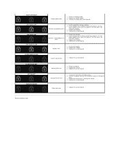
.... 2. If two modules are installed, remove one and test. Try the other slot with just the hard drive and just the optical drive. 3. Modem error 1. System board error 1. Replace the system board. Reseat the device. 2. Reseat the hard drive and optical drive. 2. Test the computer with both modules. 3. Replace the system board. Replace the system board.
.... 2. If two modules are installed, remove one and test. Try the other slot with just the hard drive and just the optical drive. 3. Modem error 1. System board error 1. Replace the system board. Reseat the device. 2. Reseat the hard drive and optical drive. 2. Test the computer with both modules. 3. Replace the system board. Replace the system board.
Service Manual
Page 19
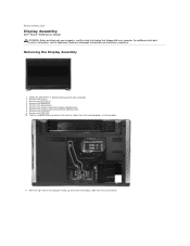
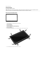
For additional safety best practices information, see the Regulatory Compliance Homepage at www.dell.com/regulatory_compliance. Remove the wireless local area network (WLAN) card. 7. Remove the wireless wide area network (WWAN) card. 8. Remove the optical drive. 6. Remove the palm rest. 10. Removing the Display Assembly 1. Remove...Follow the procedures in Before Working Inside Your Computer. 2. Back to Contents Page Display Assembly Dell™ Vostro™ 3500 Service Manual WARNING: Before working inside your computer, read the safety information that shipped with your computer.
For additional safety best practices information, see the Regulatory Compliance Homepage at www.dell.com/regulatory_compliance. Remove the wireless local area network (WLAN) card. 7. Remove the wireless wide area network (WWAN) card. 8. Remove the optical drive. 6. Remove the palm rest. 10. Removing the Display Assembly 1. Remove...Follow the procedures in Before Working Inside Your Computer. 2. Back to Contents Page Display Assembly Dell™ Vostro™ 3500 Service Manual WARNING: Before working inside your computer, read the safety information that shipped with your computer.
Service Manual
Page 23
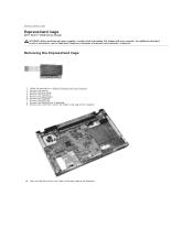
.... 7. Remove the palm rest. 8. Remove the hard drive. 5. Remove the optical drive. 6. Remove the ExpressCard, if applicable. 9. Follow the procedures in Before Working Inside Your Computer. 2. Removing the ExpressCard Cage 1. Remove the screw that shipped with your computer. Back to Contents Page ExpressCard Cage Dell™ Vostro™ 3500 Service Manual WARNING: Before working inside your...
.... 7. Remove the palm rest. 8. Remove the hard drive. 5. Remove the optical drive. 6. Remove the ExpressCard, if applicable. 9. Follow the procedures in Before Working Inside Your Computer. 2. Removing the ExpressCard Cage 1. Remove the screw that shipped with your computer. Back to Contents Page ExpressCard Cage Dell™ Vostro™ 3500 Service Manual WARNING: Before working inside your...
Service Manual
Page 32
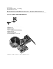
...WWAN) card. 8. Remove the keyboard. 9. For additional safety best practices information, see the Regulatory Compliance Homepage at www.dell.com/regulatory_compliance. Remove the optical drive. 6. Disconnect the fan cable from the system board. 14. Follow the procedures in Before Working Inside Your Computer. 2. ... the hard drive. 5. Remove the display assembly. 11. Remove the battery. 3. Removing the Heat Sink and Fan Assembly 1. Remove the screws that secure the heat sink and fan assembly to Contents Page Heat Sink and Fan Assembly Dell™ Vostro™ 3500 Service Manual ...
...WWAN) card. 8. Remove the keyboard. 9. For additional safety best practices information, see the Regulatory Compliance Homepage at www.dell.com/regulatory_compliance. Remove the optical drive. 6. Disconnect the fan cable from the system board. 14. Follow the procedures in Before Working Inside Your Computer. 2. ... the hard drive. 5. Remove the display assembly. 11. Remove the battery. 3. Removing the Heat Sink and Fan Assembly 1. Remove the screws that secure the heat sink and fan assembly to Contents Page Heat Sink and Fan Assembly Dell™ Vostro™ 3500 Service Manual ...
Service Manual
Page 34
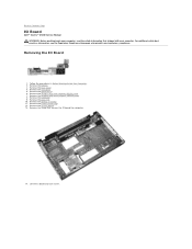
.... 3. Remove the keyboard. 9. Remove the ExpressCard cage. 12. Remove the optical drive. 6. Remove the wireless local area network (WLAN) card. 7. Remove the palm rest. 10. Remove the base cover. 4. Remove the system board. 13. Back to Contents Page IO Board Dell™ Vostro™ 3500 Service Manual WARNING: Before working inside your computer. Removing the...
.... 3. Remove the keyboard. 9. Remove the ExpressCard cage. 12. Remove the optical drive. 6. Remove the wireless local area network (WLAN) card. 7. Remove the palm rest. 10. Remove the base cover. 4. Remove the system board. 13. Back to Contents Page IO Board Dell™ Vostro™ 3500 Service Manual WARNING: Before working inside your computer. Removing the...
Service Manual
Page 39
... hard drive. 5. Remove the palm rest. 10. Removing the Display Bezel 1. For additional safety best practices information, see the Regulatory Compliance Homepage at www.dell.com/regulatory_compliance. Remove the wireless local area network (WLAN) card. 7. Using a plastic scribe, gently pry under the display bezel to Contents Page Display Bezel Dell™ Vostro™ 3500 Service...
... hard drive. 5. Remove the palm rest. 10. Removing the Display Bezel 1. For additional safety best practices information, see the Regulatory Compliance Homepage at www.dell.com/regulatory_compliance. Remove the wireless local area network (WLAN) card. 7. Using a plastic scribe, gently pry under the display bezel to Contents Page Display Bezel Dell™ Vostro™ 3500 Service...
Service Manual
Page 41
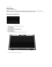
... Computer. 2. Remove the optical drive. 6. Remove the base cover 4. Back to the display assembly. 13. Carefully lift the display panel from the display assembly. Remove the screws that shipped with your computer, read the safety information that secure the display panel to Contents Page Display Panel Dell™ Vostro™ 3500 Service Manual WARNING: Before...
... Computer. 2. Remove the optical drive. 6. Remove the base cover 4. Back to the display assembly. 13. Carefully lift the display panel from the display assembly. Remove the screws that shipped with your computer, read the safety information that secure the display panel to Contents Page Display Panel Dell™ Vostro™ 3500 Service Manual WARNING: Before...
Service Manual
Page 47
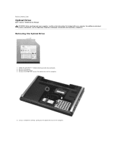
Using a screwdriver carefully, gently pry the optical drive out of the computer. Remove the battery. 3. Remove the screw that secures the optical drive to Contents Page Optical Drive Dell™ Vostro™ 3500 Service Manual WARNING: Before working inside your computer, read the safety information that shipped with your computer. For additional safety best practices information, see the ...
Using a screwdriver carefully, gently pry the optical drive out of the computer. Remove the battery. 3. Remove the screw that secures the optical drive to Contents Page Optical Drive Dell™ Vostro™ 3500 Service Manual WARNING: Before working inside your computer, read the safety information that shipped with your computer. For additional safety best practices information, see the ...
Service Manual
Page 48
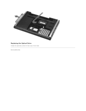
Back to Contents Page Replacing the Optical Drive To replace the optical drive, perform the above steps in reverse order.
Back to Contents Page Replacing the Optical Drive To replace the optical drive, perform the above steps in reverse order.

Service Manual
Page 49
... the screws that secure the palm rest to Contents Page Palm Rest Dell™ Vostro™ 3500 Service Manual WARNING: Before working inside your computer, read the safety information that shipped with your computer. Remove the base cover. 4. Remove the optical drive. 6. Follow the procedures in Before Working Inside Your Computer. 2. Remove the battery. 3. For...
... the screws that secure the palm rest to Contents Page Palm Rest Dell™ Vostro™ 3500 Service Manual WARNING: Before working inside your computer, read the safety information that shipped with your computer. Remove the base cover. 4. Remove the optical drive. 6. Follow the procedures in Before Working Inside Your Computer. 2. Remove the battery. 3. For...
Service Manual
Page 56
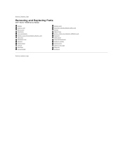
Back to Contents Page Removing and Replacing Parts Dell™ Vostro™ 3500 Service Manual Battery ExpressCard Base Cover Hard Drive Coin-Cell Battery Wireless Local Area Network (WLAN) Card Palm Rest Bluetooth Card Speaker Display Bezel Camera Heat Sink System Board Memory Card Subscriber Identity Module (SIM) Card Memory Optical Drive Wireless Wide Area Network (WWAN) Card Keyboard Audio Board Power-Button Board Display Assembly Display Panel ExpressCard Cage Processor I/O Board Back to Contents Page
Back to Contents Page Removing and Replacing Parts Dell™ Vostro™ 3500 Service Manual Battery ExpressCard Base Cover Hard Drive Coin-Cell Battery Wireless Local Area Network (WLAN) Card Palm Rest Bluetooth Card Speaker Display Bezel Camera Heat Sink System Board Memory Card Subscriber Identity Module (SIM) Card Memory Optical Drive Wireless Wide Area Network (WWAN) Card Keyboard Audio Board Power-Button Board Display Assembly Display Panel ExpressCard Cage Processor I/O Board Back to Contents Page
Service Manual
Page 57
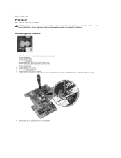
... Remove the base cover. 4. Remove the optical drive. 6. Remove the keyboard. 9. Remove the display assembly. 11. Remove the hard drive. 5. Using a flat-blade screwdriver, rotate the cam screw counterclockwise to Contents Page Processor Dell™ Vostro™ 3500 Service Manual WARNING: Before working inside your ... board. 13. For additional safety best practices information, see the Regulatory Compliance Homepage at www.dell.com/regulatory_compliance. Follow the procedures in Before Working Inside Your Computer. 2. Remove the wireless wide area network (WWAN) card. 8.
... Remove the base cover. 4. Remove the optical drive. 6. Remove the keyboard. 9. Remove the display assembly. 11. Remove the hard drive. 5. Using a flat-blade screwdriver, rotate the cam screw counterclockwise to Contents Page Processor Dell™ Vostro™ 3500 Service Manual WARNING: Before working inside your ... board. 13. For additional safety best practices information, see the Regulatory Compliance Homepage at www.dell.com/regulatory_compliance. Follow the procedures in Before Working Inside Your Computer. 2. Remove the wireless wide area network (WWAN) card. 8.
Service Manual
Page 59
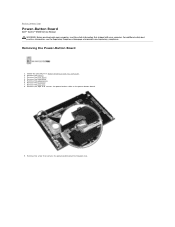
... the tape that secures the power-button cable to Contents Page Power-Button Board Dell™ Vostro™ 3500 Service Manual WARNING: Before working inside your computer. Back to the power-button board. 9. Remove the base cover. 4. Remove the optical drive. 6. Remove the battery. 3. Remove the screw that shipped with your computer, read the safety...
... the tape that secures the power-button cable to Contents Page Power-Button Board Dell™ Vostro™ 3500 Service Manual WARNING: Before working inside your computer. Back to the power-button board. 9. Remove the base cover. 4. Remove the optical drive. 6. Remove the battery. 3. Remove the screw that shipped with your computer, read the safety...


