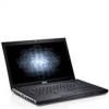
Setup and Features Information Tech Sheet
Page 1
... (2) 2 camera light 3 camera 4 display 5 volume control buttons 6 power button 7 security slot 8 cooling vent 9 video connector (VGA) 10 e-SATA connector (shared) 11 USB 2.0 connector 12 power and battery status lights 13 5-in-1 Secure Digital (SD) memory card reader 14 wireless switch 15 audio connectors 16 touchpad buttons (2) 17 speaker 18 touchpad 19 keyboard 20 keyboard and device status lights Regulatory Model: P09S, P10G, P09F, P06E Regulatory Type: P09S001, P10G001, P09F001, P06E001 FILE LOCATION: C:\Documents and Settings\kandasamy_m\Desktop\Winery_A01\Info Dev Template Last Updated...
... (2) 2 camera light 3 camera 4 display 5 volume control buttons 6 power button 7 security slot 8 cooling vent 9 video connector (VGA) 10 e-SATA connector (shared) 11 USB 2.0 connector 12 power and battery status lights 13 5-in-1 Secure Digital (SD) memory card reader 14 wireless switch 15 audio connectors 16 touchpad buttons (2) 17 speaker 18 touchpad 19 keyboard 20 keyboard and device status lights Regulatory Model: P09S, P10G, P09F, P06E Regulatory Type: P09S001, P10G001, P09F001, P06E001 FILE LOCATION: C:\Documents and Settings\kandasamy_m\Desktop\Winery_A01\Info Dev Template Last Updated...
Setup and Features Information Tech Sheet
Page 3
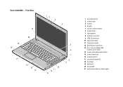
Vostro 3400/3500 - Front View 21 1 2 3 4 20 19 18 17 16 15 14 10 11 12 13 5 6 7 8 9 FILE LOCATION: C:\Documents and Settings\kandasamy_m\Desktop\Winery_A01\Info Dev 1 microphones (2) 2 camera light 3 camera 4 display 5 volume control buttons 6 power button 7 right speaker 8 network connector 9 USB 2.0 connector 10 optical drive/bay 11 fingerprint reader 12 ExpressCard connector 13 8-in-1 Secure Digital (SD) memory card reader 14 power and battery status lights 15 audio connectors 16 wireless switch 17 touchpad buttons (2) 18 touchpad 19 keyboard 20 left...
Vostro 3400/3500 - Front View 21 1 2 3 4 20 19 18 17 16 15 14 10 11 12 13 5 6 7 8 9 FILE LOCATION: C:\Documents and Settings\kandasamy_m\Desktop\Winery_A01\Info Dev 1 microphones (2) 2 camera light 3 camera 4 display 5 volume control buttons 6 power button 7 right speaker 8 network connector 9 USB 2.0 connector 10 optical drive/bay 11 fingerprint reader 12 ExpressCard connector 13 8-in-1 Secure Digital (SD) memory card reader 14 power and battery status lights 15 audio connectors 16 wireless switch 17 touchpad buttons (2) 18 touchpad 19 keyboard 20 left...
Setup and Features Information Tech Sheet
Page 5
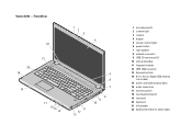
... 16 15 14 5 6 7 11 12 13 8 9 10 FILE LOCATION: C:\Documents and Settings\kandasamy_m\Desktop\Winery_A01\Info Dev 1 microphones (2) 2 camera light 3 camera 4 display 5 volume control lights 6 power button 7 right speaker 8 network connector 9 USB 2.0 connectors (2) 10 optical drive/bay 11 fingerprint reader 12 IEEE 1394 connector 13 ExpressCard slot 14 8-in-1 Secure Digital (SD) memory card reader 15 power and battery status lights 16 audio connectors 17 wireless switch 18 touchpad buttons (2) 19 touchpad 20 keyboard 21 left speaker 22 keyboard and device status lights
... 16 15 14 5 6 7 11 12 13 8 9 10 FILE LOCATION: C:\Documents and Settings\kandasamy_m\Desktop\Winery_A01\Info Dev 1 microphones (2) 2 camera light 3 camera 4 display 5 volume control lights 6 power button 7 right speaker 8 network connector 9 USB 2.0 connectors (2) 10 optical drive/bay 11 fingerprint reader 12 IEEE 1394 connector 13 ExpressCard slot 14 8-in-1 Secure Digital (SD) memory card reader 15 power and battery status lights 16 audio connectors 17 wireless switch 18 touchpad buttons (2) 19 touchpad 20 keyboard 21 left speaker 22 keyboard and device status lights
Setup and Features Information Tech Sheet
Page 7
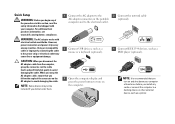
... not be included if you did not order them. 1 Connect the AC adapter to the AC adapter connector on the portable computer and to the electrical outlet. 3 Connect USB devices, such as a mouse or a keyboard (optional). 5 Open the computer display and press the power button to turn on and shut down your computer. When you wrap the AC adapter cable, ensure that you follow the angle of...
... not be included if you did not order them. 1 Connect the AC adapter to the AC adapter connector on the portable computer and to the electrical outlet. 3 Connect USB devices, such as a mouse or a keyboard (optional). 5 Open the computer display and press the power button to turn on and shut down your computer. When you wrap the AC adapter cable, ensure that you follow the angle of...
Service Manual
Page 1
... used in this document to either the entities claiming the marks and names or their products. Intel a n d Core are not applicable. Microsoft, Windows, Windows Vista, and the Windows Vista start button are not followed. All rights reserved. Dell™ Vostro™ 3500 Service Manual Working on Your Computer Specifications Removing and Replacing Parts System Setup Diagnostics Notes, Cautions, and Warnings NOTE: A NOTE indicates important information that helps you purchased a Dell™ n Series...
... used in this document to either the entities claiming the marks and names or their products. Intel a n d Core are not applicable. Microsoft, Windows, Windows Vista, and the Windows Vista start button are not followed. All rights reserved. Dell™ Vostro™ 3500 Service Manual Working on Your Computer Specifications Removing and Replacing Parts System Setup Diagnostics Notes, Cautions, and Warnings NOTE: A NOTE indicates important information that helps you purchased a Dell™ n Series...
Service Manual
Page 2
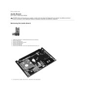
... on the audio board. Remove the hard drive assembly. 5. Remove the palm rest. 8. Remove the keyboard. 7. Remove the screw that shipped with your computer. Follow the procedures in Before Working Inside Your Computer. 2. For additional safety best practices information, see the Regulatory Compliance Homepage at www.dell.com/regulatory_compliance. Remove the base cover. 4. Back to Contents Page Audio Board Dell™ Vostro™ 3500 Service Manual WARNING: Before working inside your...
... on the audio board. Remove the hard drive assembly. 5. Remove the palm rest. 8. Remove the keyboard. 7. Remove the screw that shipped with your computer. Follow the procedures in Before Working Inside Your Computer. 2. For additional safety best practices information, see the Regulatory Compliance Homepage at www.dell.com/regulatory_compliance. Remove the base cover. 4. Back to Contents Page Audio Board Dell™ Vostro™ 3500 Service Manual WARNING: Before working inside your...
Service Manual
Page 9
... Options List. System Setup Screens Menu - Press < Left Arrow > and < Right Arrow > keys to your computer and make changes to navigate. Appears on (or restart) your computer, including installed hardware, power conservation, and security features. As an option is highlighted, the Options List lists the options that you are an expert computer user, do not change a user-selectable option such as the user password l To read the current amount of memory or set the type...
... Options List. System Setup Screens Menu - Press < Left Arrow > and < Right Arrow > keys to your computer and make changes to navigate. Appears on (or restart) your computer, including installed hardware, power conservation, and security features. As an option is highlighted, the Options List lists the options that you are an expert computer user, do not change a user-selectable option such as the user password l To read the current amount of memory or set the type...
Service Manual
Page 10
...Internal HDD Fixed Bay Device Video Controller Video BIOS Version Video Memory Panel Type Native Resolution Audio Controller WWAN Bluetooth Device Wireless Device AC Adapter Type Displays the computer model number. Displays the maximum clock speed of processor cores. Displays the processor L2 cache size. board network card. Enable or disable the IEEE 1394 port. Displays the model number of the Bluetooth® card installed on your computer. Enable or disable the ExpressCard slot. Displays the processor ID. Displays the type of the computer. Displays the BIOS...
...Internal HDD Fixed Bay Device Video Controller Video BIOS Version Video Memory Panel Type Native Resolution Audio Controller WWAN Bluetooth Device Wireless Device AC Adapter Type Displays the computer model number. Displays the maximum clock speed of processor cores. Displays the processor L2 cache size. board network card. Enable or disable the IEEE 1394 port. Displays the model number of the Bluetooth® card installed on your computer. Enable or disable the ExpressCard slot. Displays the processor ID. Displays the type of the computer. Displays the BIOS...

Service Manual
Page 11
... Power Management USB Wake Support Wake On LAN Post Behaviour Adapter Warnings Fast Boot Keyboard Click Wireless Internal Bluetooth Internal WLAN Internal WWAN Allows the clock speed of the processor to be remotely turned on. Enable or disable the wireless WAN module. The hard drive password is enabled even when the hard drive is installed on Boot Password Bypass Password Change Computrace HDD Password Configuration Displays the current service tag of the computer. However, you must enter the passwords if you to set an admin password. Enable or disable the keyboard sound...
... Power Management USB Wake Support Wake On LAN Post Behaviour Adapter Warnings Fast Boot Keyboard Click Wireless Internal Bluetooth Internal WLAN Internal WWAN Allows the clock speed of the processor to be remotely turned on. Enable or disable the wireless WAN module. The hard drive password is enabled even when the hard drive is installed on Boot Password Bypass Password Change Computrace HDD Password Configuration Displays the current service tag of the computer. However, you must enter the passwords if you to set an admin password. Enable or disable the keyboard sound...
Service Manual
Page 12
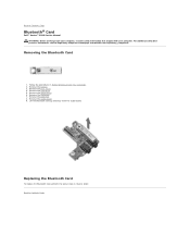
... audio board. 9. Replacing the Bluetooth Card To replace the Bluetooth card, perform the above steps in Before Working Inside Your Computer. 2. Back to Contents Page Bluetooth® Card Dell™ Vostro™ 3500 Service Manual WARNING: Before working inside your computer, read the safety information that shipped with your computer. Remove the hard drive. 5. Remove the optical drive. 6. Lift the Bluetooth card up and away from the audio board. Follow the procedures in reverse order. Removing the Bluetooth Card 1. Remove the keyboard. 7. Remove...
... audio board. 9. Replacing the Bluetooth Card To replace the Bluetooth card, perform the above steps in Before Working Inside Your Computer. 2. Back to Contents Page Bluetooth® Card Dell™ Vostro™ 3500 Service Manual WARNING: Before working inside your computer, read the safety information that shipped with your computer. Remove the hard drive. 5. Remove the optical drive. 6. Lift the Bluetooth card up and away from the audio board. Follow the procedures in reverse order. Removing the Bluetooth Card 1. Remove the keyboard. 7. Remove...
Service Manual
Page 13
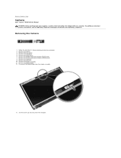
... Camera Dell™ Vostro™ 3500 Service Manual WARNING: Before working inside your computer, read the safety information that shipped with your computer. Follow the procedures in Before Working Inside Your Computer. 2. Remove the battery. 3. Remove the keyboard. 9. Remove the display assembly. 11. Remove the hard drive. 5. Remove the wireless wide area network (WWAN) card. 8. Disconnect the camera cable from the computer. Remove the base cover. 4. Remove the palm rest. 10. Removing the Camera 1. Remove the wireless local area network (WLAN) card...
... Camera Dell™ Vostro™ 3500 Service Manual WARNING: Before working inside your computer, read the safety information that shipped with your computer. Follow the procedures in Before Working Inside Your Computer. 2. Remove the battery. 3. Remove the keyboard. 9. Remove the display assembly. 11. Remove the hard drive. 5. Remove the wireless wide area network (WWAN) card. 8. Disconnect the camera cable from the computer. Remove the base cover. 4. Remove the palm rest. 10. Removing the Camera 1. Remove the wireless local area network (WLAN) card...
Service Manual
Page 17
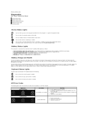
... tray and select Disable Bluetooth Radio. l Blue light on when wireless networking is enabled. If no lights appear, the battery has no -POST situation. Turns on - Replace the system board. 3. To check battery health using the charge gauge, press and hold the status button on the battery charge gauge for at a time in a power management mode. l Alternately blinking amber light with AC adapter present. Turns on when the Scroll Lock function is in each slot. 3. To turn on the...
... tray and select Disable Bluetooth Radio. l Blue light on when wireless networking is enabled. If no lights appear, the battery has no -POST situation. Turns on - Replace the system board. 3. To check battery health using the charge gauge, press and hold the status button on the battery charge gauge for at a time in a power management mode. l Alternately blinking amber light with AC adapter present. Turns on when the Scroll Lock function is in each slot. 3. To turn on the...
Service Manual
Page 18
... the video card/system board. Test the other slot with both modules. 3. Replace the system board. Replace the system board. Replace the system board. Modem error 1. Option ROM error 1. Test the computer with both modules. 3. Storage device error 1. Replace the system board. Reseat the modem. 2. FLASH-ON-FLASH OFF-FLASH-OFF ON-FLASH-ON OFF-FLASH-FLASH FLASH-FLASH-FLASH FLASH-FLASH-OFF OFF-ON-OFF FLASH-FLASH-ON Back to Contents Page Display panel error 1. Reseat the hard drive and optical drive. 2. Install compatible memory modules. 2. Replace the system board. Replace the...
... the video card/system board. Test the other slot with both modules. 3. Replace the system board. Replace the system board. Replace the system board. Modem error 1. Option ROM error 1. Test the computer with both modules. 3. Storage device error 1. Replace the system board. Reseat the modem. 2. FLASH-ON-FLASH OFF-FLASH-OFF ON-FLASH-ON OFF-FLASH-FLASH FLASH-FLASH-FLASH FLASH-FLASH-OFF OFF-ON-OFF FLASH-FLASH-ON Back to Contents Page Display panel error 1. Reseat the hard drive and optical drive. 2. Install compatible memory modules. 2. Replace the system board. Replace the...
Service Manual
Page 19
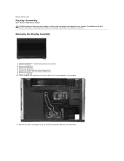
... release the antenna cables from the system board. For additional safety best practices information, see the Regulatory Compliance Homepage at www.dell.com/regulatory_compliance. Remove the optical drive. 6. Remove the wireless local area network (WLAN) card. 7. Remove the keyboard. 9. Follow the procedures in Before Working Inside Your Computer. 2. Remove the base cover. 4. Back to Contents Page Display Assembly Dell™ Vostro™ 3500 Service Manual WARNING: Before working inside your computer...
... release the antenna cables from the system board. For additional safety best practices information, see the Regulatory Compliance Homepage at www.dell.com/regulatory_compliance. Remove the optical drive. 6. Remove the wireless local area network (WLAN) card. 7. Remove the keyboard. 9. Follow the procedures in Before Working Inside Your Computer. 2. Remove the base cover. 4. Back to Contents Page Display Assembly Dell™ Vostro™ 3500 Service Manual WARNING: Before working inside your computer...
Service Manual
Page 32
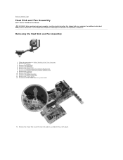
... board. Remove the battery. 3. Remove the palm rest. 10. Removing the Heat Sink and Fan Assembly 1. Remove the base cover. 4. Remove the wireless wide area network (WWAN) card. 8. For additional safety best practices information, see the Regulatory Compliance Homepage at www.dell.com/regulatory_compliance. Follow the procedures in Before Working Inside Your Computer. 2. Remove the keyboard. 9. Remove the system board. 13. Remove the hard drive. 5. Disconnect the fan cable from the system board. 14. Remove...
... board. Remove the battery. 3. Remove the palm rest. 10. Removing the Heat Sink and Fan Assembly 1. Remove the base cover. 4. Remove the wireless wide area network (WWAN) card. 8. For additional safety best practices information, see the Regulatory Compliance Homepage at www.dell.com/regulatory_compliance. Follow the procedures in Before Working Inside Your Computer. 2. Remove the keyboard. 9. Remove the system board. 13. Remove the hard drive. 5. Disconnect the fan cable from the system board. 14. Remove...
Service Manual
Page 43
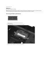
Removing the Memory Module(s) 1. Remove the battery. 3. Follow the procedures in Before Working Inside Your Computer. 2. Remove the memory module from its connector on the system board. Push apart the memory retention clips to Contents Page Memory Dell™ Vostro™ 3500 Service Manual WARNING: Before working inside your computer, read the safety information that shipped with your computer. Back to release the memory module. 5. Remove the base cover. 4. For additional safety best practices...
Removing the Memory Module(s) 1. Remove the battery. 3. Follow the procedures in Before Working Inside Your Computer. 2. Remove the memory module from its connector on the system board. Push apart the memory retention clips to Contents Page Memory Dell™ Vostro™ 3500 Service Manual WARNING: Before working inside your computer, read the safety information that shipped with your computer. Back to release the memory module. 5. Remove the base cover. 4. For additional safety best practices...
Service Manual
Page 56
Back to Contents Page Removing and Replacing Parts Dell™ Vostro™ 3500 Service Manual Battery ExpressCard Base Cover Hard Drive Coin-Cell Battery Wireless Local Area Network (WLAN) Card Palm Rest Bluetooth Card Speaker Display Bezel Camera Heat Sink System Board Memory Card Subscriber Identity Module (SIM) Card Memory Optical Drive Wireless Wide Area Network (WWAN) Card Keyboard Audio Board Power-Button Board Display Assembly Display Panel ExpressCard Cage Processor I/O Board Back to Contents Page
Back to Contents Page Removing and Replacing Parts Dell™ Vostro™ 3500 Service Manual Battery ExpressCard Base Cover Hard Drive Coin-Cell Battery Wireless Local Area Network (WLAN) Card Palm Rest Bluetooth Card Speaker Display Bezel Camera Heat Sink System Board Memory Card Subscriber Identity Module (SIM) Card Memory Optical Drive Wireless Wide Area Network (WWAN) Card Keyboard Audio Board Power-Button Board Display Assembly Display Panel ExpressCard Cage Processor I/O Board Back to Contents Page
Service Manual
Page 69
Wireless ExpressCard wireless local area network (WLAN) wireless wide area network (WWAN) worldwide interoperability for WiMax Drives Hard drive Optical drive Display Type Active area (X/Y) Dimensions: Height Width Diagonal Maximum resolution Maximum brightness Operating angle Refresh rate Viewing angles: Horizontal Vertical Pixel pitch Keyboard Number of keys Layout Touchpad Active area: X-axis Y-axis Battery Type Charge time with computer off Operating time SATA 2 HDD SATA 2 Mobile HDD DVD+/-RW Blu-ray 15.60-inch anti glare (AG...
Wireless ExpressCard wireless local area network (WLAN) wireless wide area network (WWAN) worldwide interoperability for WiMax Drives Hard drive Optical drive Display Type Active area (X/Y) Dimensions: Height Width Diagonal Maximum resolution Maximum brightness Operating angle Refresh rate Viewing angles: Horizontal Vertical Pixel pitch Keyboard Number of keys Layout Touchpad Active area: X-axis Y-axis Battery Type Charge time with computer off Operating time SATA 2 HDD SATA 2 Mobile HDD DVD+/-RW Blu-ray 15.60-inch anti glare (AG...
Service Manual
Page 76
... l #1 Phillips screwdriver l Small plastic scribe l Flash BIOS update program CD Turning Off Your Computer CAUTION: To avoid losing data, save and close all open files and exit all open programs before you work surface is flat and clean to prevent the computer cover from the network device. 4. Remove the main battery (see Hard Drive). Open the display. 10. CAUTION: Before touching anything inside your computer, read the...
... l #1 Phillips screwdriver l Small plastic scribe l Flash BIOS update program CD Turning Off Your Computer CAUTION: To avoid losing data, save and close all open files and exit all open programs before you work surface is flat and clean to prevent the computer cover from the network device. 4. Remove the main battery (see Hard Drive). Open the display. 10. CAUTION: Before touching anything inside your computer, read the...

Service Manual
Page 77
... cable into the network device and then plug it into the computer. 2. Connect your computer. Replace the battery. 4. Connect any external devices, such as a port replicator, battery slice, or media base, and replace any cards, such as shown below, and then click Shut Down. Connect any external devices, cards, and cables before turning on your operating system, press and hold the power button for other Dell computers. 1. CAUTION: To avoid damage to the computer, use batteries...
... cable into the network device and then plug it into the computer. 2. Connect your computer. Replace the battery. 4. Connect any external devices, such as a port replicator, battery slice, or media base, and replace any cards, such as shown below, and then click Shut Down. Connect any external devices, cards, and cables before turning on your operating system, press and hold the power button for other Dell computers. 1. CAUTION: To avoid damage to the computer, use batteries...


