
User Manual
Page 2
... 18. headphone connector 2 touchpad disable LED 22. security cable slot 2. HDMI connector 6. fingerprint reader 13. hard disk status light 20. power button Figure 2. cooling vents 5. battery status light 19. power connector 3. powered USB 3.0 connector 7. touchpad 15. VGA connector 4. 7. optical drive 11. keyboard 23. Secure Digital (SD) memory-card reader 16. power...
... 18. headphone connector 2 touchpad disable LED 22. security cable slot 2. HDMI connector 6. fingerprint reader 13. hard disk status light 20. power button Figure 2. cooling vents 5. battery status light 19. power connector 3. powered USB 3.0 connector 7. touchpad 15. VGA connector 4. 7. optical drive 11. keyboard 23. Secure Digital (SD) memory-card reader 16. power...

User Manual
Page 3
...Vostro 3560 - microphone 2. optical drive 11. ExpressCard slot 14. power status light 21. display 5. touchpad disable LED 22. Front And Back View Figure 3. network connector 9. keyboard 23. Secure Digital (SD) memory-card reader 16. hard disk status light 20. fingerprint reader 13. battery... status light 19. Windows Mobility Center 6. wireless status light 18. camera status light 4. touchpad 15. touchpad buttons (2) 17. camera 3. Dell Support Center 7. USB 3.0 connectors (2) 10.
...Vostro 3560 - microphone 2. optical drive 11. ExpressCard slot 14. power status light 21. display 5. touchpad disable LED 22. Front And Back View Figure 3. network connector 9. keyboard 23. Secure Digital (SD) memory-card reader 16. hard disk status light 20. fingerprint reader 13. battery... status light 19. Windows Mobility Center 6. wireless status light 18. camera status light 4. touchpad 15. touchpad buttons (2) 17. camera 3. Dell Support Center 7. USB 3.0 connectors (2) 10.

User Manual
Page 6
...mm (1.27 inches) 375.00 mm (14.76 inches) 259.00 mm (10.19 inches) 2.61 kg (5.75 lb) 6 Input voltage Coin-cell battery 100 VAC to a docking device or other external device, such as a printer. For more information regarding the configuration of your computer, click Start → ... at least once before you install any cards or connect the computer to 240 VAC 3 V CR2032 lithium coin cell Physical Vostro 3460 Height Width Depth Weight (with battery pack and optical drive) Vostro 3560 Height Width Depth Weight (with your computer. Power AC Adapter 65 W and 90 W NOTE: 65 W AC adapter...
...mm (1.27 inches) 375.00 mm (14.76 inches) 259.00 mm (10.19 inches) 2.61 kg (5.75 lb) 6 Input voltage Coin-cell battery 100 VAC to a docking device or other external device, such as a printer. For more information regarding the configuration of your computer, click Start → ... at least once before you install any cards or connect the computer to 240 VAC 3 V CR2032 lithium coin cell Physical Vostro 3460 Height Width Depth Weight (with battery pack and optical drive) Vostro 3560 Height Width Depth Weight (with your computer. Power AC Adapter 65 W and 90 W NOTE: 65 W AC adapter...

Owner's Manual
Page 3
......6 After Working Inside Your Computer...6 2 Removing and Installing Components 9 Recommended Tools...9 Removing the Security Digital (SD) Card...9 Installing the Secure Digital Card...9 Removing the Battery...9 Installing the Battery...10 Removing the Base Cover...10 Installing the Base Cover...12 Removing the Memory...12 Installing the Memory...12 Removing the Optical Drive...13...
......6 After Working Inside Your Computer...6 2 Removing and Installing Components 9 Recommended Tools...9 Removing the Security Digital (SD) Card...9 Installing the Secure Digital Card...9 Removing the Battery...9 Installing the Battery...10 Removing the Base Cover...10 Installing the Base Cover...12 Removing the Memory...12 Installing the Memory...12 Removing the Optical Drive...13...

Owner's Manual
Page 4
...-Sink Fan...31 Installing the Heat-Sink Fan...31 Removing the System Board...32 Installing the System Board...34 Removing the Coin-Cell Battery...34 Installing the Coin-Cell Battery...35 Removing the Heat Sink...35 Installing the Heat Sink...36 Removing the Speakers...36 Installing the Speakers...37 Removing the Processor... Existing System and/or Setup Password 49 4 Diagnostics...51 Enhanced Pre-Boot System Assessment (ePSA) Diagnostics 51 5 Troubleshooting Your Computer 53 Device Status Lights...53 Battery Status Lights...53 Diagnostic Beep Codes...53 6 Specifications...55 7 Contacting...
...-Sink Fan...31 Installing the Heat-Sink Fan...31 Removing the System Board...32 Installing the System Board...34 Removing the Coin-Cell Battery...34 Installing the Coin-Cell Battery...35 Removing the Heat Sink...35 Installing the Heat Sink...36 Removing the Speakers...36 Installing the Speakers...37 Removing the Processor... Existing System and/or Setup Password 49 4 Diagnostics...51 Enhanced Pre-Boot System Assessment (ePSA) Diagnostics 51 5 Troubleshooting Your Computer 53 Device Status Lights...53 Battery Status Lights...53 Diagnostic Beep Codes...53 6 Specifications...55 7 Contacting...
Owner's Manual
Page 5
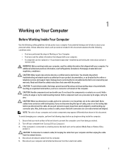
...metal surface, such as authorized in your computer. WARNING: Before working inside your computer, read the safety information that is not authorized by Dell is not covered by its edges or by a certified service technician. You should only perform troubleshooting and simple repairs as a connector on...Many repairs may appear differently than shown in this document assumes that your personal safety. Hold a component such as the optional Media Base or Battery Slice, undock it. NOTE: The color of the computer. If the computer is flat and clean to a docking device (docked) such ...
...metal surface, such as authorized in your computer. WARNING: Before working inside your computer, read the safety information that is not authorized by Dell is not covered by its edges or by a certified service technician. You should only perform troubleshooting and simple repairs as a connector on...Many repairs may appear differently than shown in this document assumes that your personal safety. Hold a component such as the optional Media Base or Battery Slice, undock it. NOTE: The color of the computer. If the computer is flat and clean to a docking device (docked) such ...
Owner's Manual
Page 6
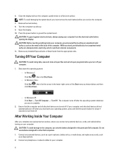
.... 6 Remove any installed ExpressCards or Smart Cards from the electrical outlet before you shut down your computer. 1. Remove the main battery. 8. CAUTION: To guard against electrical shock, always unplug your computer from the appropriate slots. Turning Off Your Computer CAUTION: To...system, press and hold the power button for about 4 seconds to the computer, use batteries designed for this particular Dell computer. Do not use only the battery designed for other Dell computers. 1. After Working Inside Your Computer After you complete any external devices, cards, ...
.... 6 Remove any installed ExpressCards or Smart Cards from the electrical outlet before you shut down your computer. 1. Remove the main battery. 8. CAUTION: To guard against electrical shock, always unplug your computer from the appropriate slots. Turning Off Your Computer CAUTION: To...system, press and hold the power button for about 4 seconds to the computer, use batteries designed for this particular Dell computer. Do not use only the battery designed for other Dell computers. 1. After Working Inside Your Computer After you complete any external devices, cards, ...

Owner's Manual
Page 7
Turn on your computer and all attached devices to their electrical outlets. 5. Replace the battery. 4. Connect your computer. 7 CAUTION: To connect a network cable, first plug the cable into the network device and then plug it into the computer. 3.
Turn on your computer and all attached devices to their electrical outlets. 5. Replace the battery. 4. Connect your computer. 7 CAUTION: To connect a network cable, first plug the cable into the network device and then plug it into the computer. 3.

Owner's Manual
Page 9
...the SD card to remove or install the components from the computer. Follow the procedures in Before Working Inside Your Computer. 2. Removing the Battery 1. Slide the SD card out of the computer. Press in on how to release it clicks into the slot until it from your... computer. Installing the Secure Digital Card 1. Follow the procedures in After Working Inside Your Computer. Slide the battery latches to release the battery. 9 Push the SD card into place. 2. Follow the procedures in this document may require the following tools: • Small flat...
...the SD card to remove or install the components from the computer. Follow the procedures in Before Working Inside Your Computer. 2. Removing the Battery 1. Slide the SD card out of the computer. Press in on how to release it clicks into the slot until it from your... computer. Installing the Secure Digital Card 1. Follow the procedures in After Working Inside Your Computer. Slide the battery latches to release the battery. 9 Push the SD card into place. 2. Follow the procedures in this document may require the following tools: • Small flat...

Owner's Manual
Page 10
Removing the Base Cover 1. Slide the battery into its slot until it clicks into place. 2. Remove the screw(s) that secures the cover to the computer. Lift the cover upwards. 10 Follow the procedures in Before Working Inside Your Computer. 2. Remove the battery. 3. 3. Installing the Battery 1. Lift and remove the battery from the computer. Follow the procedures in After Working Inside Your Computer.
Removing the Base Cover 1. Slide the battery into its slot until it clicks into place. 2. Remove the screw(s) that secures the cover to the computer. Lift the cover upwards. 10 Follow the procedures in Before Working Inside Your Computer. 2. Remove the battery. 3. 3. Installing the Battery 1. Lift and remove the battery from the computer. Follow the procedures in After Working Inside Your Computer.

Owner's Manual
Page 12
... the edge of the base cover on the computer. 2. Follow the procedures in After Working Inside Your Computer. Install the battery. 4. Removing the Memory 1. Installing the Base Cover 1. Pry the retention clips away from its connector. Lift and remove the memory module from the memory module ...
... the edge of the base cover on the computer. 2. Follow the procedures in After Working Inside Your Computer. Install the battery. 4. Removing the Memory 1. Installing the Base Cover 1. Pry the retention clips away from its connector. Lift and remove the memory module from the memory module ...
Owner's Manual
Page 13
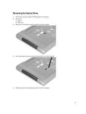
Use a flat-headed screw driver to the computer. 4. Follow the procedures in Before Working Inside Your Computer. 2. Remove the screw that secures the optical drive to pry the optical drive out of the computer. 5. Removing the Optical Drive 1. Slide the optical drive outwards and remove it from the computer. 13 Remove the: a) battery b) base cover 3.
Use a flat-headed screw driver to the computer. 4. Follow the procedures in Before Working Inside Your Computer. 2. Remove the screw that secures the optical drive to pry the optical drive out of the computer. 5. Removing the Optical Drive 1. Slide the optical drive outwards and remove it from the computer. 13 Remove the: a) battery b) base cover 3.

Owner's Manual
Page 14
... bracket. 2. 6. Remove the optical-drive bracket from the optical drive. Slide the optical drive into the compartment on the chassis. 3. Install the: a) base cover b) battery 5. Installing the Optical Drive 1. Follow the procedures in After Working Inside Your Computer. Remove the screws that secure the hard drive to the computer. 14... Follow the procedures in Before Working Inside Your Computer. 2. Removing the Hard Drive 1. Remove the: a) battery b) base cover 3. Remove the screws that secure the optical-drive bracket.
... bracket. 2. 6. Remove the optical-drive bracket from the optical drive. Slide the optical drive into the compartment on the chassis. 3. Install the: a) base cover b) battery 5. Installing the Optical Drive 1. Follow the procedures in After Working Inside Your Computer. Remove the screws that secure the hard drive to the computer. 14... Follow the procedures in Before Working Inside Your Computer. 2. Removing the Hard Drive 1. Remove the: a) battery b) base cover 3. Remove the screws that secure the optical-drive bracket.

Owner's Manual
Page 16
... Your Computer. Disconnect the hard-drive cable. Connect the hard-drive cable to hard-drive bracket. Install the: a) base cover b) battery 8. Follow the procedures in Before Working Inside Your Computer. 2. Remove the battery. 3. Installing the Hard Drive 1. Remove the screws securing the hard drive to the hard drive. 4. Tighten the screws that...
... Your Computer. Disconnect the hard-drive cable. Connect the hard-drive cable to hard-drive bracket. Install the: a) base cover b) battery 8. Follow the procedures in Before Working Inside Your Computer. 2. Remove the battery. 3. Installing the Hard Drive 1. Remove the screws securing the hard drive to the hard drive. 4. Tighten the screws that...

Owner's Manual
Page 18
Install the battery. 6. Press down until the keyboard clicks into place. 5. Connect the mylar tape to the system board. 2. Follow the procedures in its compartment. 4. Insert the keyboard in Before Working On Your Computer. 2. Connect the keyboard data cable to the system board. 3. Removing the Palmrest 1. Installing the Keyboard 1. Follow the procedures in After Working Inside Your Computer. Remove the: a) battery b) base cover c) memory d) optical drive e) hard drive f) keyboard 3. Remove the screws from the bottom of the computer. 18
Install the battery. 6. Press down until the keyboard clicks into place. 5. Connect the mylar tape to the system board. 2. Follow the procedures in its compartment. 4. Insert the keyboard in Before Working On Your Computer. 2. Connect the keyboard data cable to the system board. 3. Removing the Palmrest 1. Installing the Keyboard 1. Follow the procedures in After Working Inside Your Computer. Remove the: a) battery b) base cover c) memory d) optical drive e) hard drive f) keyboard 3. Remove the screws from the bottom of the computer. 18

Owner's Manual
Page 23
... to engage the tabs on the bottom of the palmrest, press downwards to the computer. 4. Install the: a) keyboard b) hard drive c) optical drive d) memory e) base cover f) battery 10. Follow the procedures in After Working Inside Your Computer. Installing the Palmrest 1. Starting from the computer. 23 Align the palmrest on its position on...
... to engage the tabs on the bottom of the palmrest, press downwards to the computer. 4. Install the: a) keyboard b) hard drive c) optical drive d) memory e) base cover f) battery 10. Follow the procedures in After Working Inside Your Computer. Installing the Palmrest 1. Starting from the computer. 23 Align the palmrest on its position on...

Owner's Manual
Page 24
Tighten the screw to the computer. 4. Install the: a) palmrest b) keyboard c) base cover d) battery 5. Follow the procedures in After Working Inside Your Computer. Remove the: a) battery b) keyboard c) palmrest 3. Removing the Display Assembly 1. Lift up the display from the computer. 24 Follow the procedures in Before Working Inside Your Computer. 2. Remove the ...
Tighten the screw to the computer. 4. Install the: a) palmrest b) keyboard c) base cover d) battery 5. Follow the procedures in After Working Inside Your Computer. Remove the: a) battery b) keyboard c) palmrest 3. Removing the Display Assembly 1. Lift up the display from the computer. 24 Follow the procedures in Before Working Inside Your Computer. 2. Remove the ...

Owner's Manual
Page 25
... the Display-Hinge Cover 1. Tighten the screws to secure the display assembly to its location on the computer base. 2. Remove the: a) battery b) base cover c) memory d) optical drive e) hard drive f) keyboard g) palmrest h) WLAN card i) display assembly 3. Align the display assembly to the chassis. 3. Follow the procedures in Before ...
... the Display-Hinge Cover 1. Tighten the screws to secure the display assembly to its location on the computer base. 2. Remove the: a) battery b) base cover c) memory d) optical drive e) hard drive f) keyboard g) palmrest h) WLAN card i) display assembly 3. Align the display assembly to the chassis. 3. Follow the procedures in Before ...

Owner's Manual
Page 26
Tighten the screws to secure the display-hinge cover to the computer. 3. Pry and remove the display-hinge cover from the computer. Press the display-hinge cover till it clicks into place. 2. Install the: a) display assembly b) WLAN card c) palmrest d) keyboard e) hard drive f) optical drive g) memory h) base cover i) battery 26 4. Installing the Display-Hinge Cover 1.
Tighten the screws to secure the display-hinge cover to the computer. 3. Pry and remove the display-hinge cover from the computer. Press the display-hinge cover till it clicks into place. 2. Install the: a) display assembly b) WLAN card c) palmrest d) keyboard e) hard drive f) optical drive g) memory h) base cover i) battery 26 4. Installing the Display-Hinge Cover 1.

Owner's Manual
Page 27
... the procedures in Before Working Inside Your Computer. 2. Pry up the sides of the display bezel and separate the bezel from the display. Remove the: a) battery b) keyboard c) palmrest d) display-hinge cover 27 Follow the procedures in After Working Inside Your Computer. 4. Removing the Display Bezel 1. Align the display bezel on the...
... the procedures in Before Working Inside Your Computer. 2. Pry up the sides of the display bezel and separate the bezel from the display. Remove the: a) battery b) keyboard c) palmrest d) display-hinge cover 27 Follow the procedures in After Working Inside Your Computer. 4. Removing the Display Bezel 1. Align the display bezel on the...

