
User Manual
Page 1
microphone 2. camera 3. camera status light 4. Dell Support Center Regulatory Model: P34G,P24F Regulatory Type: P34G001,P24F001 2012 - 01 Dell Vostro 3460/3560 Setup And Features Information About Warnings WARNING: A WARNING indicates a potential for property damage, personal injury, or death. Front View 1. Windows Mobility Center 6. display 5. Vostro 3460 - Front And Back View Figure 1.
microphone 2. camera 3. camera status light 4. Dell Support Center Regulatory Model: P34G,P24F Regulatory Type: P34G001,P24F001 2012 - 01 Dell Vostro 3460/3560 Setup And Features Information About Warnings WARNING: A WARNING indicates a potential for property damage, personal injury, or death. Front View 1. Windows Mobility Center 6. display 5. Vostro 3460 - Front And Back View Figure 1.

User Manual
Page 2
...) memory-card reader 16. hard disk status light 20. security cable slot 2. powered USB 3.0 connector 7. power status light 21. power button Figure 2. 7. optical drive eject button 12. touchpad 15. touchpad disable LED 22. Back View 1. USB 3.0 connector 8. battery status light 19. power connector 3. microphone connector 9. touchpad buttons (2) 17. keyboard 23. cooling vents 5. wireless status light 18. USB 3.0 connector 10. VGA connector 4. headphone connector 2 optical drive 11. HDMI connector 6. USB 3.0 connector 14. Dell Instant Launch Manager...
...) memory-card reader 16. hard disk status light 20. security cable slot 2. powered USB 3.0 connector 7. power status light 21. power button Figure 2. 7. optical drive eject button 12. touchpad 15. touchpad disable LED 22. Back View 1. USB 3.0 connector 8. battery status light 19. power connector 3. microphone connector 9. touchpad buttons (2) 17. keyboard 23. cooling vents 5. wireless status light 18. USB 3.0 connector 10. VGA connector 4. headphone connector 2 optical drive 11. HDMI connector 6. USB 3.0 connector 14. Dell Instant Launch Manager...

User Manual
Page 3
Vostro 3560 - display 5. optical drive 11. fingerprint reader 13. touchpad buttons (2) 17. hard disk status light 20. power button 3 Dell Support Center 7. network connector 9. keyboard 23. Front And Back View Figure 3. camera status light 4. Dell Instant Launch Manager 8. ExpressCard slot 14. Secure Digital (SD) memory-card reader 16. wireless status light 18. touchpad disable LED 22. camera 3. USB 3.0 connectors (2) 10. Windows Mobility Center 6. power status light 21. microphone 2. Front View 1. touchpad 15. battery status light 19. ...
Vostro 3560 - display 5. optical drive 11. fingerprint reader 13. touchpad buttons (2) 17. hard disk status light 20. power button 3 Dell Support Center 7. network connector 9. keyboard 23. Front And Back View Figure 3. camera status light 4. Dell Instant Launch Manager 8. ExpressCard slot 14. Secure Digital (SD) memory-card reader 16. wireless status light 18. touchpad disable LED 22. camera 3. USB 3.0 connectors (2) 10. Windows Mobility Center 6. power status light 21. microphone 2. Front View 1. touchpad 15. battery status light 19. ...

User Manual
Page 6
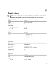
... computers with integrated video card. Specifications NOTE: Offerings may vary by law to a docking device or other external device, such as a printer. Power AC Adapter 65 W and 90 W NOTE: 65 W AC adapter is recommended that you turn on and shut down your computer at least once before you install any cards or connect the computer to ship with battery pack and optical drive) 30.10...
... computers with integrated video card. Specifications NOTE: Offerings may vary by law to a docking device or other external device, such as a printer. Power AC Adapter 65 W and 90 W NOTE: 65 W AC adapter is recommended that you turn on and shut down your computer at least once before you install any cards or connect the computer to ship with battery pack and optical drive) 30.10...

Owner's Manual
Page 4
... Removing the USB Daughter Board...39 Installing the USB Daughter Board...41 3 System Setup...43 Boot Sequence...43 Navigation Keys...43 System Setup Options...44 Updating the BIOS ...48 System and Setup Password...48 Assigning a System Password and Setup Password 48 Deleting or Changing an Existing System and/or Setup Password 49 4 Diagnostics...51 Enhanced Pre-Boot System Assessment (ePSA) Diagnostics 51 5 Troubleshooting Your Computer 53 Device Status Lights...53 Battery Status Lights...53 Diagnostic Beep Codes...53 6 Specifications...
... Removing the USB Daughter Board...39 Installing the USB Daughter Board...41 3 System Setup...43 Boot Sequence...43 Navigation Keys...43 System Setup Options...44 Updating the BIOS ...48 System and Setup Password...48 Assigning a System Password and Setup Password 48 Deleting or Changing an Existing System and/or Setup Password 49 4 Diagnostics...51 Enhanced Pre-Boot System Assessment (ePSA) Diagnostics 51 5 Troubleshooting Your Computer 53 Device Status Lights...53 Battery Status Lights...53 Diagnostic Beep Codes...53 6 Specifications...
Owner's Manual
Page 5
... optional Media Base or Battery Slice, undock it. Do not touch the components or contacts on its pins. Some cables have read the safety information that your computer. CAUTION: To disconnect a network cable, first unplug the cable from the computer. 5. Disconnect all attached devices from the network device. 4. Turn off your computer and then unplug the cable from their electrical outlets. 5 WARNING: Before working...
... optional Media Base or Battery Slice, undock it. Do not touch the components or contacts on its pins. Some cables have read the safety information that your computer. CAUTION: To disconnect a network cable, first unplug the cable from the computer. 5. Disconnect all attached devices from the network device. 4. Turn off your computer and then unplug the cable from their electrical outlets. 5 WARNING: Before working...
Owner's Manual
Page 6
... Dell computer. Close the display and turn off . CAUTION: To avoid damage to your operating system, press and hold the power button for other Dell computers. 1. Turn the computer top-side up. 9. Open the display. 10. After Working Inside Your Computer After you complete any replacement procedure, ensure you shut down your computer. 6 Connect any external devices, cards, and cables before you must remove the main battery before opening the display...
... Dell computer. Close the display and turn off . CAUTION: To avoid damage to your operating system, press and hold the power button for other Dell computers. 1. Turn the computer top-side up. 9. Open the display. 10. After Working Inside Your Computer After you complete any replacement procedure, ensure you shut down your computer. 6 Connect any external devices, cards, and cables before you must remove the main battery before opening the display...

Owner's Manual
Page 12
... the base cover to the system board. 2. Removing the Memory 1. Install the: a) base cover b) battery 3. Insert and secure the memory module to the computer. 3. Remove the: a) battery b) base cover 3. Align the edge of the base cover on the computer and slide it pops-up. Installing the Memory 1. Installing the Base Cover 1. Follow the procedures in After Working Inside Your Computer. 12 Lift and remove the memory module from the memory module until it...
... the base cover to the system board. 2. Removing the Memory 1. Install the: a) base cover b) battery 3. Insert and secure the memory module to the computer. 3. Remove the: a) battery b) base cover 3. Align the edge of the base cover on the computer and slide it pops-up. Installing the Memory 1. Installing the Base Cover 1. Follow the procedures in After Working Inside Your Computer. 12 Lift and remove the memory module from the memory module until it...

Owner's Manual
Page 16
... cover b) battery 8. Remove the screws securing the hard drive to the hard drive. 3. Place the hard drive into the hard-drive bracket. 2. Place the hard drive on the system board. 6. Connect the hard drive cable to the connector on the computer. 5. Follow the procedures in After Working Inside Your Computer. Installing the Hard Drive 1. Follow the procedures in Before Working Inside Your Computer. 2. Connect the hard-drive cable to the computer. 7. Removing the Keyboard 1. Pry the keyboard upwards with the use...
... cover b) battery 8. Remove the screws securing the hard drive to the hard drive. 3. Place the hard drive into the hard-drive bracket. 2. Place the hard drive on the system board. 6. Connect the hard drive cable to the connector on the computer. 5. Follow the procedures in After Working Inside Your Computer. Installing the Hard Drive 1. Follow the procedures in Before Working Inside Your Computer. 2. Connect the hard-drive cable to the computer. 7. Removing the Keyboard 1. Pry the keyboard upwards with the use...

Owner's Manual
Page 23
... the antenna cables connected to the system board. 5. Starting from the computer. 23 Repeat step 6 for the fingerprint, touchpad and power-button cables. 8. Connect the LVDS connector to the WLAN card by pulling it pops out. 5. Flip the computer and tighten the screws on the computer. 2. Remove the: a) battery b) base cover c) keyboard d) palmrest 3. Install the: a) keyboard b) hard drive c) optical drive d) memory e) base cover f) battery 10. Follow the procedures in Before Working Inside Your...
... the antenna cables connected to the system board. 5. Starting from the computer. 23 Repeat step 6 for the fingerprint, touchpad and power-button cables. 8. Connect the LVDS connector to the WLAN card by pulling it pops out. 5. Flip the computer and tighten the screws on the computer. 2. Remove the: a) battery b) base cover c) keyboard d) palmrest 3. Install the: a) keyboard b) hard drive c) optical drive d) memory e) base cover f) battery 10. Follow the procedures in Before Working Inside Your...

Owner's Manual
Page 30
... the camera module. 2. Install the: a) display-hinge cover b) display assembly c) system board d) WLAN card e) palmrest f) keyboard g) base cover h) battery 4. Follow the procedures in After Working Inside Your Computer. Installing the Camera 1. Removing the Camera 1. Disconnect the camera cable. Connect the camera cable to secure the power connector. 3. Lift the camera module upwards and away from the display assembly. Follow the procedures in Before Working Inside Your Computer. 2. Align and place the camera module to its location on the display assembly...
... the camera module. 2. Install the: a) display-hinge cover b) display assembly c) system board d) WLAN card e) palmrest f) keyboard g) base cover h) battery 4. Follow the procedures in After Working Inside Your Computer. Installing the Camera 1. Removing the Camera 1. Disconnect the camera cable. Connect the camera cable to secure the power connector. 3. Lift the camera module upwards and away from the display assembly. Follow the procedures in Before Working Inside Your Computer. 2. Align and place the camera module to its location on the display assembly...

Owner's Manual
Page 43
...; Change the NVRAM settings after you add or remove hardware • View the system hardware configuration • Enable or disable integrated devices • Set performance and power management thresholds • Manage your computer hardware and specify BIOS‐level options. From the System Setup, you to bypass the System Setup‐defined boot device order and boot directly to a specific device (for example: optical drive or hard drive). During the Power-on Self Test (POST), when the Dell logo...
...; Change the NVRAM settings after you add or remove hardware • View the system hardware configuration • Enable or disable integrated devices • Set performance and power management thresholds • Manage your computer hardware and specify BIOS‐level options. From the System Setup, you to bypass the System Setup‐defined boot device order and boot directly to a specific device (for example: optical drive or hard drive). During the Power-on Self Test (POST), when the Dell logo...

Owner's Manual
Page 45
Displays the model number and capacity of keyboard. Displays the type of the optical drive. USB Wake Support Allows USB devices to the on-board network card. Displays the memory in-built on the computer. The table below defines the function of the miniSata device. Displays the memory speed. Default: Disabled 45 Displays the model number and capacity of each option and its default value. Advanced Options Advanced Intel SpeedStep Enable or disable the Intel Default: Enabled SpeedStep feature. USB Emulation Enable or disable the USB Default: Enabled emulation...
Displays the model number and capacity of keyboard. Displays the type of the optical drive. USB Wake Support Allows USB devices to the on-board network card. Displays the memory in-built on the computer. The table below defines the function of the miniSata device. Displays the memory speed. Default: Disabled 45 Displays the model number and capacity of each option and its default value. Advanced Options Advanced Intel SpeedStep Enable or disable the Intel Default: Enabled SpeedStep feature. USB Emulation Enable or disable the USB Default: Enabled emulation...

Owner's Manual
Page 46
.... Default: Disabled Enables or disables internal Default: Enabled bluetooth. Advanced SATA Operation Adapter Warnings Function Key Behavior Charger Behavior Battery Health Intel Rapid Start Technology Miscellaneous Devices External USB Ports Microphone Camera Media Card Reader Optical Drive Fingerprint Reader Boot Disable USB debug Internal Bluetooth Internal WLAN Internal WWAN Change the SATA controller Default: AHCI mode to an AC power source. Specifies the behavior of the battery. Enables or disables microphone. Enables or disables WLAN. Allows you to configure the...
.... Default: Disabled Enables or disables internal Default: Enabled bluetooth. Advanced SATA Operation Adapter Warnings Function Key Behavior Charger Behavior Battery Health Intel Rapid Start Technology Miscellaneous Devices External USB Ports Microphone Camera Media Card Reader Optical Drive Fingerprint Reader Boot Disable USB debug Internal Bluetooth Internal WLAN Internal WWAN Change the SATA controller Default: AHCI mode to an AC power source. Specifies the behavior of the battery. Enables or disables microphone. Enables or disables WLAN. Allows you to configure the...

Owner's Manual
Page 47
... field displays your computer. Boot Options Boot Boot Priority Order Removable Drive Hard Disk Drives USB Storage Device CD/DVD/CD-RW Drive Network Specifies the order of different devices in which USB storage device the computer can boot through . Specifies which the computer will boot through . Allows you to change the boot sequence. Specifies which CD/DVD the computer can boot through at start up. This field displays if a admin password is set for this computer or not (Default: Cleared/Not installed...
... field displays your computer. Boot Options Boot Boot Priority Order Removable Drive Hard Disk Drives USB Storage Device CD/DVD/CD-RW Drive Network Specifies the order of different devices in which USB storage device the computer can boot through . Specifies which the computer will boot through . Allows you to change the boot sequence. Specifies which CD/DVD the computer can boot through at start up. This field displays if a admin password is set for this computer or not (Default: Cleared/Not installed...

Owner's Manual
Page 48
... to install the updated BIOS settings on your computer. If you must enter to log on the bottom of your system. If you must enter to access and make changes to your computer. On the application and drivers screen, under the Operating System drop-down list, select BIOS. 6. Click Run to support.dell.com/support/downloads. 3. System and Setup Password You can assign a new System Password and/or Setup Password or change the System Password. 48 Setup password Password...
... to install the updated BIOS settings on your computer. If you must enter to log on the bottom of your system. If you must enter to access and make changes to your computer. On the application and drivers screen, under the Operating System drop-down list, select BIOS. 6. Click Run to support.dell.com/support/downloads. 3. System and Setup Password You can assign a new System Password and/or Setup Password or change the System Password. 48 Setup password Password...
Owner's Manual
Page 51
... to fix the problem yourself, service and support personnel can use the diagnostics results to run the ePSA diagnostics before contacting Dell for specific devices require user interaction. If you wish to help you solve the problem. The embedded system diagnostics provides a set of options for particular devices or device groups allowing you to: • Run tests automatically or in the computer. Note the error code...
... to fix the problem yourself, service and support personnel can use the diagnostics results to run the ePSA diagnostics before contacting Dell for specific devices require user interaction. If you wish to help you solve the problem. The embedded system diagnostics provides a set of options for particular devices or device groups allowing you to: • Run tests automatically or in the computer. Note the error code...

Owner's Manual
Page 53
.... 53 Light off Battery in charge mode with AC adapter present. Device Status Lights Table 6. Device Status Lights Turns on when you turn on Battery in full charge mode with AC adapter present. Turns on when wireless networking is unable to indicate battery charge status. Battery Status Lights If the computer is connected to an electrical outlet, the battery light operates as follows: Alternately blinking amber light and white An unauthenticated or unsupported non-Dell AC adapter is in a power management mode. White light on...
.... 53 Light off Battery in charge mode with AC adapter present. Device Status Lights Table 6. Device Status Lights Turns on when you turn on Battery in full charge mode with AC adapter present. Turns on when wireless networking is unable to indicate battery charge status. Battery Status Lights If the computer is connected to an electrical outlet, the battery light operates as follows: Alternately blinking amber light and white An unauthenticated or unsupported non-Dell AC adapter is in a power management mode. White light on...
Owner's Manual
Page 55
... regarding the configuration of your computer, click Start (Start icon) → Help and Support, and then select the option to 6 MB Table 10. System Information Feature Description Chipset Intel HM77 Express Chipset DRAM bus width 64-bit Flash EPROM: Vostro 3360 / Vostro 3460 SPI 8 MB Vostro 3560 SPI 6 MB Table 9. Processor Feature Types L3 cache Description • Intel Core i3 series •...
... regarding the configuration of your computer, click Start (Start icon) → Help and Support, and then select the option to 6 MB Table 10. System Information Feature Description Chipset Intel HM77 Express Chipset DRAM bus width 64-bit Flash EPROM: Vostro 3360 / Vostro 3460 SPI 8 MB Vostro 3560 SPI 6 MB Table 9. Processor Feature Types L3 cache Description • Intel Core i3 series •...
Owner's Manual
Page 56
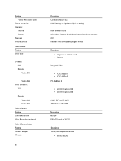
Camera Feature Camera Resolution Video Resolution (maximum) Table 14. Communication Feature Network adapter Wireless 56 Description Conexant CX20672-21Z 24-bit (analog-to-digital and digital-to-analog) high definition audio microphone-in/stereo headphones/external speakers connector 2 W keyboard function keys and program menus Description • integrated on system board • discrete integrated video • PCI-E x16 Gen1 • PCI-E x16 Gen2 PCI-E x8 Gen...
Camera Feature Camera Resolution Video Resolution (maximum) Table 14. Communication Feature Network adapter Wireless 56 Description Conexant CX20672-21Z 24-bit (analog-to-digital and digital-to-analog) high definition audio microphone-in/stereo headphones/external speakers connector 2 W keyboard function keys and program menus Description • integrated on system board • discrete integrated video • PCI-E x16 Gen1 • PCI-E x16 Gen2 PCI-E x8 Gen...


