Owner's Manual
Page 3
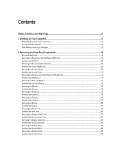
... Network (WLAN) Card 11 Installing the WLAN Card...11 Removing the Coin-Cell Battery...11 Installing the Coin-Cell Battery...12 Removing the Memory...12 Installing the Memory...12 Removing the Keyboard...12 Installing the Keyboard...14 Removing the Palmrest...14 Installing the Palmrest...17 Removing the Battery...18 Installing the Battery...
... Network (WLAN) Card 11 Installing the WLAN Card...11 Removing the Coin-Cell Battery...11 Installing the Coin-Cell Battery...12 Removing the Memory...12 Installing the Memory...12 Removing the Keyboard...12 Installing the Keyboard...14 Removing the Palmrest...14 Installing the Palmrest...17 Removing the Battery...18 Installing the Battery...
Owner's Manual
Page 12
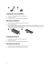
...at 45-degree angle. Remove the screw that secures the keyboard to the system board. 2. Install the access panel. 3. Removing the Memory 1. Push the coin-call battery into its connector on the system board. 2. Follow the procedures in Before Working Inside Your Computer.... 2. Install the access panel. 3. Installing the Memory 1. Follow the procedures in After Working Inside Your Computer. Removing the Keyboard 1. Follow the procedures in After Working Inside Your Computer. ...
...at 45-degree angle. Remove the screw that secures the keyboard to the system board. 2. Install the access panel. 3. Removing the Memory 1. Push the coin-call battery into its connector on the system board. 2. Follow the procedures in Before Working Inside Your Computer.... 2. Install the access panel. 3. Installing the Memory 1. Follow the procedures in After Working Inside Your Computer. Removing the Keyboard 1. Follow the procedures in After Working Inside Your Computer. ...
Owner's Manual
Page 39
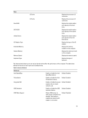
... Integrated NIC Enable or disable the power Default: Enabled supply to the on the computer. Default: Disabled 39 Displays the memory in-built on -board network card. Advanced Options Advanced Intel SpeedStep Enable or disable the Intel Default: Enabled SpeedStep feature....connected. Displays the model number and capacity of the hard drive. Main Fixed HDD SATA ODD mSata Device AC Adapter Type Extended Memory System Memory Memory Speed Keyboard Type L2 Cache L3 Cache Displays the processor L2 cache size. Displays the model number and capacity of the optical ...
... Integrated NIC Enable or disable the power Default: Enabled supply to the on the computer. Default: Disabled 39 Displays the memory in-built on -board network card. Advanced Options Advanced Intel SpeedStep Enable or disable the Intel Default: Enabled SpeedStep feature....connected. Displays the model number and capacity of the hard drive. Main Fixed HDD SATA ODD mSata Device AC Adapter Type Extended Memory System Memory Memory Speed Keyboard Type L2 Cache L3 Cache Displays the processor L2 cache size. Displays the model number and capacity of the optical ...
Owner's Manual
Page 46
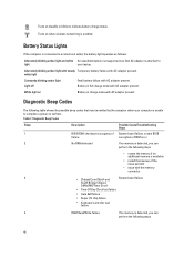
...connected to an electrical outlet, the battery light operates as follows: Alternately blinking amber light and white An unauthenticated or unsupported non-Dell AC adapter is unable to complete a power on steadily or blinks to light your computer is attached to indicate battery charge status.... Turns on Battery in charge mode with the memory connector 3 • Chipset Error (North and System board failure South Bridge Chipset, DMA/IMR/Timer Error) • Time-Of-Day Clock...
...connected to an electrical outlet, the battery light operates as follows: Alternately blinking amber light and white An unauthenticated or unsupported non-Dell AC adapter is unable to complete a power on steadily or blinks to light your computer is attached to indicate battery charge status.... Turns on Battery in charge mode with the memory connector 3 • Chipset Error (North and System board failure South Bridge Chipset, DMA/IMR/Timer Error) • Time-Of-Day Clock...
Owner's Manual
Page 47
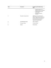
Beep 5 6 7 8 Description Real-time clock power fail Video BIOS Test Failure Processor Failure Display Possible Cause/Troubleshooting Steps • reseat the memory if an additional memory is available • install that will involve replacing the system board) Video card failure Processor failure Display failure 47 Reseat the battery. If issue persists, there can be an issue with the coin-cell battery or the connector (that memory if the issue persists • issue with the memory connector CMOS battery failure.
Beep 5 6 7 8 Description Real-time clock power fail Video BIOS Test Failure Processor Failure Display Possible Cause/Troubleshooting Steps • reseat the memory if an additional memory is available • install that will involve replacing the system board) Video card failure Processor failure Display failure 47 Reseat the battery. If issue persists, there can be an issue with the coin-cell battery or the connector (that memory if the issue persists • issue with the memory connector CMOS battery failure.
Owner's Manual
Page 49
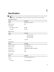
... by region. Table 8. System Information Feature Description Chipset Intel HM77 Express Chipset DRAM bus width 64-bit Flash EPROM: Vostro 3360 / Vostro 3460 SPI 8 MB Vostro 3560 SPI 6 MB Table 9. Memory Feature Memory connector Memory capacity Memory type Minimum memory Maximum memory Description two SODIMM slots 2 GB, 4 GB, 6 GB, or 8 GB DDR3 SDRAM (1333 MHz and 1600 MHz) 2 GB 8 GB...
... by region. Table 8. System Information Feature Description Chipset Intel HM77 Express Chipset DRAM bus width 64-bit Flash EPROM: Vostro 3360 / Vostro 3460 SPI 8 MB Vostro 3560 SPI 6 MB Table 9. Memory Feature Memory connector Memory capacity Memory type Minimum memory Maximum memory Description two SODIMM slots 2 GB, 4 GB, 6 GB, or 8 GB DDR3 SDRAM (1333 MHz and 1600 MHz) 2 GB 8 GB...


