User Manual
Page 1
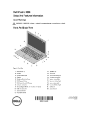
... 12. fingerprint reader 13. touchpad 15. power status light 20. Dell Instant Launch Manager 8. USB 3.0 connector 11. battery status light 18. hard disk status light 19. camera status light 4. Dell Support Center 7. in-1 media card reader 10. wireless status light 17... touchpad buttons (2) 16. microphone (2) 2. Windows Mobility Center 6. Secure Digital (SD) 8- touchpad status light 21. Dell Vostro 3360 Setup And Features Information About Warnings WARNING: A WARNING indicates a potential for property damage, personal injury, or death. camera 3. display 5.
... 12. fingerprint reader 13. touchpad 15. power status light 20. Dell Instant Launch Manager 8. USB 3.0 connector 11. battery status light 18. hard disk status light 19. camera status light 4. Dell Support Center 7. in-1 media card reader 10. wireless status light 17... touchpad buttons (2) 16. microphone (2) 2. Windows Mobility Center 6. Secure Digital (SD) 8- touchpad status light 21. Dell Vostro 3360 Setup And Features Information About Warnings WARNING: A WARNING indicates a potential for property damage, personal injury, or death. camera 3. display 5.
User Manual
Page 3
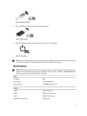
USB Connector 4. For more information regarding the configuration of your computer, click Start → Help and Support and select the option to ship with battery pack) 19.20 mm (0.75 inch) 332.00 mm (13.07 inches) 232.50 mm (9.15 inches) 1.68 kg (3.70 lb) 3 ...Network Connector 3. Connect USB devices, such as a printer. The following specifications are only those required by region. Power AC Adapter Input voltage Coin-cell battery 65 W 100 VAC to a docking device or other external device, such as a mouse or keyboard (optional). Open the computer display and press the ...
USB Connector 4. For more information regarding the configuration of your computer, click Start → Help and Support and select the option to ship with battery pack) 19.20 mm (0.75 inch) 332.00 mm (13.07 inches) 232.50 mm (9.15 inches) 1.68 kg (3.70 lb) 3 ...Network Connector 3. Connect USB devices, such as a printer. The following specifications are only those required by region. Power AC Adapter Input voltage Coin-cell battery 65 W 100 VAC to a docking device or other external device, such as a mouse or keyboard (optional). Open the computer display and press the ...
Owner's Manual
Page 3
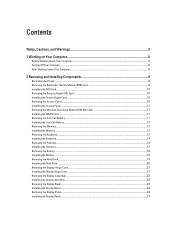
......11 Removing the Wireless Local Area Network (WLAN) Card 11 Installing the WLAN Card...11 Removing the Coin-Cell Battery...11 Installing the Coin-Cell Battery...12 Removing the Memory...12 Installing the Memory...12 Removing the Keyboard...12 Installing the Keyboard...14 Removing the Palmrest......14 Installing the Palmrest...17 Removing the Battery...18 Installing the Battery...19 Removing the Hard Drive...19 Installing the Hard Drive...20 Removing the Display-Hinge Cover...21 Installing the Display ...
......11 Removing the Wireless Local Area Network (WLAN) Card 11 Installing the WLAN Card...11 Removing the Coin-Cell Battery...11 Installing the Coin-Cell Battery...12 Removing the Memory...12 Installing the Memory...12 Removing the Keyboard...12 Installing the Keyboard...14 Removing the Palmrest......14 Installing the Palmrest...17 Removing the Battery...18 Installing the Battery...19 Removing the Hard Drive...19 Installing the Hard Drive...20 Removing the Display-Hinge Cover...21 Installing the Display ...
Owner's Manual
Page 4
... Deleting or Changing an Existing System and/or Setup Password 43 4 Diagnostics...45 Enhanced Pre-Boot System Assessment (ePSA) Diagnostics 45 Device Status Lights...45 Battery Status Lights...46 Diagnostic Beep Codes...46 5 Specifications...49 6 Contacting...
... Deleting or Changing an Existing System and/or Setup Password 43 4 Diagnostics...45 Enhanced Pre-Boot System Assessment (ePSA) Diagnostics 45 Device Status Lights...45 Battery Status Lights...46 Diagnostic Beep Codes...46 5 Specifications...49 6 Contacting...
Owner's Manual
Page 5
...and then unplug the cable from being scratched. 2. Disconnect all attached devices from your computer (see the Regulatory Compliance Homepage at www.dell.com/ regulatory_compliance CAUTION: Many repairs may appear differently than shown in this document assumes that the following safety guidelines to help to a... Do not touch the components or contacts on the back of your warranty. Hold a component such as the optional Media Base or Battery Slice, undock it. Some cables have read the safety information that shipped with your computer. 1 Working on Your Computer Before Working ...
...and then unplug the cable from being scratched. 2. Disconnect all attached devices from your computer (see the Regulatory Compliance Homepage at www.dell.com/ regulatory_compliance CAUTION: Many repairs may appear differently than shown in this document assumes that the following safety guidelines to help to a... Do not touch the components or contacts on the back of your warranty. Hold a component such as the optional Media Base or Battery Slice, undock it. Some cables have read the safety information that shipped with your computer. 1 Working on Your Computer Before Working ...
Owner's Manual
Page 6
Shut down on your computer. 6 Do not use only the battery designed for this particular Dell computer. Turn the computer top-side up. 9. Open the display. 10. While you work surface. The computer turns off when you connect any external devices,... cards, and cables before opening the display. After Working Inside Your Computer After you complete any telephone or network cables to the computer, use batteries...
Shut down on your computer. 6 Do not use only the battery designed for this particular Dell computer. Turn the computer top-side up. 9. Open the display. 10. While you work surface. The computer turns off when you connect any external devices,... cards, and cables before opening the display. After Working Inside Your Computer After you complete any telephone or network cables to the computer, use batteries...
Owner's Manual
Page 7
Replace the battery. 4. Turn on your computer and all attached devices to their electrical outlets. 5. Connect your computer. 7 CAUTION: To connect a network cable, first plug the cable into the network device and then plug it into the computer. 3.
Replace the battery. 4. Turn on your computer and all attached devices to their electrical outlets. 5. Connect your computer. 7 CAUTION: To connect a network cable, first plug the cable into the network device and then plug it into the computer. 3.
Owner's Manual
Page 11
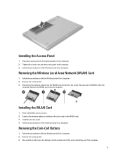
...Removing the Wireless Local Area Network (WLAN) Card 1. Follow the procedures in Before Working Inside Your Computer. 2. Use a plastic scribe to pry the battery from the computer. Follow the procedures in After Working Inside Your Computer. Remove the WLAN card from the socket and lift the coin-cell... battery out of the computer. 11 Removing the Coin-Cell Battery 1. Disconnect the antenna cables from the WLAN card and remove the screw that secures the WLAN card to the...
...Removing the Wireless Local Area Network (WLAN) Card 1. Follow the procedures in Before Working Inside Your Computer. 2. Use a plastic scribe to pry the battery from the computer. Follow the procedures in After Working Inside Your Computer. Remove the WLAN card from the socket and lift the coin-cell... battery out of the computer. 11 Removing the Coin-Cell Battery 1. Disconnect the antenna cables from the WLAN card and remove the screw that secures the WLAN card to the...
Owner's Manual
Page 12
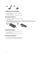
Remove the access panel. 3. Install the access panel. 3. Follow the procedures in After Working Inside Your Computer. Push the coin-call battery into its connector on the system board by drawing the module from its slot on each end of the memory module connector until the memory ... in After Working Inside Your Computer. Removing the Keyboard 1. Installing the Memory 1. Follow the procedures in Before Working Inside Your Computer. 2. Installing the Coin-Cell Battery 1. Use your fingertips to spread apart the securing clips on the system board. 2.
Remove the access panel. 3. Install the access panel. 3. Follow the procedures in After Working Inside Your Computer. Push the coin-call battery into its connector on the system board by drawing the module from its slot on each end of the memory module connector until the memory ... in After Working Inside Your Computer. Removing the Keyboard 1. Installing the Memory 1. Follow the procedures in Before Working Inside Your Computer. 2. Installing the Coin-Cell Battery 1. Use your fingertips to spread apart the securing clips on the system board. 2.
Owner's Manual
Page 18
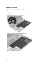
Remove the: a) access panel b) keyboard c) palmrest 3. Remove the screws that secure the battery to the system board. 5. Disconnect the battery cable from the computer. 18 Remove the battery from the system board. 4. Removing the Battery 1. Follow the procedures in Before Working Inside Your Computer. 2.
Remove the: a) access panel b) keyboard c) palmrest 3. Remove the screws that secure the battery to the system board. 5. Disconnect the battery cable from the computer. 18 Remove the battery from the system board. 4. Removing the Battery 1. Follow the procedures in Before Working Inside Your Computer. 2.
Owner's Manual
Page 19
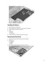
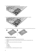
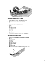
Install: a) palmrest b) keyboard c) access panel 5. Follow the procedures in Before Working Inside Your Computer. 2. Remove the screws that secure the battery to the computer. 19 Follow the procedures in After Working Inside Your Computer. Removing the Hard Drive 1. Remove the: a) access panel b) keyboard c) palmrest d) battery 3. Installing the Battery 1. Replace and tighten the screws that secure the hard drive to the computer. 3. Connect the battery cable to the system board. 4. Place the battery into the battery bay. 2.
Install: a) palmrest b) keyboard c) access panel 5. Follow the procedures in Before Working Inside Your Computer. 2. Remove the screws that secure the battery to the computer. 19 Follow the procedures in After Working Inside Your Computer. Removing the Hard Drive 1. Remove the: a) access panel b) keyboard c) palmrest d) battery 3. Installing the Battery 1. Replace and tighten the screws that secure the hard drive to the computer. 3. Connect the battery cable to the system board. 4. Place the battery into the battery bay. 2.
Owner's Manual
Page 20
... drive to disconnect the hard-drive cable. 5. Remove the screws that secure the hard-drive bracket to the hard drive. 2. Installing the Hard Drive 1. Install: a) battery b) palmrest c) keyboard d) access panel 5. 4. Follow the procedures in After Working Inside Your Computer. 20 Tighten the screws to secure the hard drive bracket to the...
... drive to disconnect the hard-drive cable. 5. Remove the screws that secure the hard-drive bracket to the hard drive. 2. Installing the Hard Drive 1. Install: a) battery b) palmrest c) keyboard d) access panel 5. 4. Follow the procedures in After Working Inside Your Computer. 20 Tighten the screws to secure the hard drive bracket to the...
Owner's Manual
Page 22
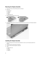
... the system board and tighten the screws to secure the display assembly to the computer. Install : a) display hinge cover b) battery c) palmrest d) keyboard 22 Follow the procedures in Before Working Inside Your Computer. 2. Release the antenna cables from the system board... and remove the screws that secure the display assembly to the computer. 2. Remove the: a) access panel b) keyboard c) palmrest d) battery e) display hinge cover 3. Disconnect the display cable from their routing tabs. 4. Installing the Display Assembly 1. Removing the Display Assembly 1. Thread ...
... the system board and tighten the screws to secure the display assembly to the computer. Install : a) display hinge cover b) battery c) palmrest d) keyboard 22 Follow the procedures in Before Working Inside Your Computer. 2. Release the antenna cables from the system board... and remove the screws that secure the display assembly to the computer. 2. Remove the: a) access panel b) keyboard c) palmrest d) battery e) display hinge cover 3. Disconnect the display cable from their routing tabs. 4. Installing the Display Assembly 1. Removing the Display Assembly 1. Thread ...
Owner's Manual
Page 23
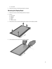
Remove: a) access panel b) keyboard c) palmrest d) battery e) display assembly 3. Lift the display bezel and remove it from the display assembly. 23 Follow the procedures in Before Working Inside Your Computer. 2. Using a plastic scribe, pry under the display bezel to release it from the display assembly. 4. Removing the Display Bezel 1. Follow the procedures in After Working Inside Your Computer. e) access panel 5.
Remove: a) access panel b) keyboard c) palmrest d) battery e) display assembly 3. Lift the display bezel and remove it from the display assembly. 23 Follow the procedures in Before Working Inside Your Computer. 2. Using a plastic scribe, pry under the display bezel to release it from the display assembly. 4. Removing the Display Bezel 1. Follow the procedures in After Working Inside Your Computer. e) access panel 5.
Owner's Manual
Page 24
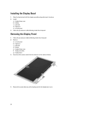
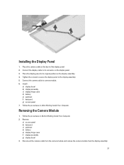
... in Before Working Inside Your Computer. 2. Removing the Display Panel 1. Disconnect the camera cable from its connector on the camera module. 4. Install : a) display hinge cover b) battery c) palmrest d) keyboard e) access panel 3. Align the display bezel with the display assembly and gently snap it into place. 2. Installing the Display Bezel 1. Remove: a) access panel...
... in Before Working Inside Your Computer. 2. Removing the Display Panel 1. Disconnect the camera cable from its connector on the camera module. 4. Install : a) display hinge cover b) battery c) palmrest d) keyboard e) access panel 3. Align the display bezel with the display assembly and gently snap it into place. 2. Installing the Display Bezel 1. Remove: a) access panel...
Owner's Manual
Page 27
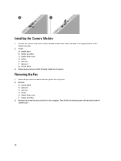
Tighten the screws to secure the display panel to camera module. 6. Remove: a) access panel b) keyboard c) palmrest d) battery e) display hinge cover f) display assembly g) display bezel 3. Place the camera cable on the display assembly. 4. Connect the... display panel to its original position on the back of the display panel. 2. Install : a) display bezel b) display assembly c) display hinge cover d) battery e) palmrest f) keyboard g) access panel 7. Follow the procedures in Before Working Inside Your Computer. 2. Removing the Camera Module 1. Installing the Display Panel ...
Tighten the screws to secure the display panel to camera module. 6. Remove: a) access panel b) keyboard c) palmrest d) battery e) display hinge cover f) display assembly g) display bezel 3. Place the camera cable on the display assembly. 4. Connect the... display panel to its original position on the back of the display panel. 2. Install : a) display bezel b) display assembly c) display hinge cover d) battery e) palmrest f) keyboard g) access panel 7. Follow the procedures in Before Working Inside Your Computer. 2. Removing the Camera Module 1. Installing the Display Panel ...
Owner's Manual
Page 28
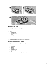
Follow the procedures in Before Working Inside Your Computer. 2. Removing the Fan 1. Remove: a) access panel b) keyboard c) palmrest d) battery e) display hinge cover f) display assembly 3. Connect the camera cable to the camera module and place the camera module to the computer. Follow ... the fan to its original position on the display assembly. 2. Installing the Camera Module 1. Install : a) display bezel b) display assembly c) display hinge cover d) battery e) palmrest f) keyboard g) access panel 3. Then, lift the fan and disconnect the fan cable from the system board. 28
Follow the procedures in Before Working Inside Your Computer. 2. Removing the Fan 1. Remove: a) access panel b) keyboard c) palmrest d) battery e) display hinge cover f) display assembly 3. Connect the camera cable to the camera module and place the camera module to the computer. Follow ... the fan to its original position on the display assembly. 2. Installing the Camera Module 1. Install : a) display bezel b) display assembly c) display hinge cover d) battery e) palmrest f) keyboard g) access panel 3. Then, lift the fan and disconnect the fan cable from the system board. 28
Owner's Manual
Page 29
Removing the System Board 1. Follow the procedures in After Working Inside Your Computer. Follow the procedures in Before Working Inside Your Computer. 2. Install : a) display assembly b) display hinge cover c) battery d) palmrest e) keyboard f) access panel 4. Installing the Fan 1. Disconnect the I/O cable from the I/O daughter board. 29 Remove: a) access panel b) keyboard c) palmrest d) display hinge cover e) display assembly f) fan 3. Tighten the screws to secure the fan to the system board. 2. Connect the fan cable to the computer. 3.
Removing the System Board 1. Follow the procedures in After Working Inside Your Computer. Follow the procedures in Before Working Inside Your Computer. 2. Install : a) display assembly b) display hinge cover c) battery d) palmrest e) keyboard f) access panel 4. Installing the Fan 1. Disconnect the I/O cable from the I/O daughter board. 29 Remove: a) access panel b) keyboard c) palmrest d) display hinge cover e) display assembly f) fan 3. Tighten the screws to secure the fan to the system board. 2. Connect the fan cable to the computer. 3.
Owner's Manual
Page 31
... to secure the system board to the system board. 2. Connect the I/O board cable to the system board. 31 Install : a) fan b) display assembly c) display hinge cover d) battery e) palmrest f) keyboard g) access panel 6. Remove the screws that secure the heat sink to the I/O board. 5. Follow the procedures in Before Working Inside Your Computer. 2. Installing...
... to secure the system board to the system board. 2. Connect the I/O board cable to the system board. 31 Install : a) fan b) display assembly c) display hinge cover d) battery e) palmrest f) keyboard g) access panel 6. Remove the screws that secure the heat sink to the I/O board. 5. Follow the procedures in Before Working Inside Your Computer. 2. Installing...
Owner's Manual
Page 32
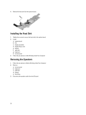
Follow the procedures in After Working Inside Your Computer. Remove: a) access panel b) keyboard c) palmrest d) battery e) hard drive 3. Disconnect the speaker cable from the system board, Installing the Heat Sink 1. Install : a) system board b) fan c) display assembly d) display hinge cover e) battery f) palmrest g) keyboard h) access panel 3. Follow the procedures in Before Working Inside Your Computer. 2. Removing the Speakers 1. Tighten the screws to secure the heat sink to the system board. 2. 4. Remove the heat sink from the I/O board. 32
Follow the procedures in After Working Inside Your Computer. Remove: a) access panel b) keyboard c) palmrest d) battery e) hard drive 3. Disconnect the speaker cable from the system board, Installing the Heat Sink 1. Install : a) system board b) fan c) display assembly d) display hinge cover e) battery f) palmrest g) keyboard h) access panel 3. Follow the procedures in Before Working Inside Your Computer. 2. Removing the Speakers 1. Tighten the screws to secure the heat sink to the system board. 2. 4. Remove the heat sink from the I/O board. 32


