Page 2
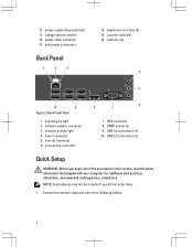
...adapter connector 3. HDMI connector 9. link-integrity light 2. USB 2.0 connectors (2) Quick Setup WARNING: Before you did not order them. 1. power-supply diagnostic light 11. expansion card slots (4) 15. VGA connector 8. 10. back panel connectors Back Panel 14. line-in this section, read... the safety information that shipped with your computer. microphone connector 7. For additional best practices information, see www.dell.com/regulatory_compliance NOTE: Some devices may not be included if you begin any of the following cables: 2 security cable slot...
...adapter connector 3. HDMI connector 9. link-integrity light 2. USB 2.0 connectors (2) Quick Setup WARNING: Before you did not order them. 1. power-supply diagnostic light 11. expansion card slots (4) 15. VGA connector 8. 10. back panel connectors Back Panel 14. line-in this section, read... the safety information that shipped with your computer. microphone connector 7. For additional best practices information, see www.dell.com/regulatory_compliance NOTE: Some devices may not be included if you begin any of the following cables: 2 security cable slot...

Page 4
... computer, click Start → Help and Support and select the option to 240 V 3 V, CR2032 lithium coin cell NOTE: Heat dissipation is calculated by using the power supply wattage rating. 4 For more information regarding the configuration of your computer. Figure 8. 4. Figure 9. The following specifications are only those required by region. Press the...
... computer, click Start → Help and Support and select the option to 240 V 3 V, CR2032 lithium coin cell NOTE: Heat dissipation is calculated by using the power supply wattage rating. 4 For more information regarding the configuration of your computer. Figure 8. 4. Figure 9. The following specifications are only those required by region. Press the...
Owner's Manual
Page 3
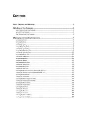
... Local Area Network (WLAN) Card 15 Removing the Card Reader...16 Installing the Card Reader...17 Removing the Power Supply Unit (PSU)...17 Installing the Power Supply Unit (PSU)...18 Removing the Power Switch...18 Installing the Power Switch...19 Removing the I/O Panel...19 Installing the I/O Panel...21 Removing the Processor...21 Installing the Processor...23...
... Local Area Network (WLAN) Card 15 Removing the Card Reader...16 Installing the Card Reader...17 Removing the Power Supply Unit (PSU)...17 Installing the Power Supply Unit (PSU)...18 Removing the Power Switch...18 Installing the Power Switch...19 Removing the I/O Panel...19 Installing the I/O Panel...21 Removing the Processor...21 Installing the Processor...23...

Owner's Manual
Page 17
...the hard drive (s), optical drive (s), and system board. 4. Slide the multimedia-card reader in After Working Inside Your Computer. Disconnect the power-supply cables connected to the system board. 5. Remove the screws that secure the multimedia-card reader to the drive cage. 3. Press the ...of the computer. 17 Follow the procedures in through the front of the computer. 5. Replace the: a) front panel b) cover 6. Removing the Power Supply Unit (PSU) 1. Follow the procedures in Before Working Inside Your Computer. 2. Route the cable thorough the metal clip(s), if present, to ...
...the hard drive (s), optical drive (s), and system board. 4. Slide the multimedia-card reader in After Working Inside Your Computer. Disconnect the power-supply cables connected to the system board. 5. Remove the screws that secure the multimedia-card reader to the drive cage. 3. Press the ...of the computer. 17 Follow the procedures in through the front of the computer. 5. Replace the: a) front panel b) cover 6. Removing the Power Supply Unit (PSU) 1. Follow the procedures in Before Working Inside Your Computer. 2. Route the cable thorough the metal clip(s), if present, to ...

Owner's Manual
Page 18
... 1. Follow the procedures in Before Working Inside Your Computer. 2. Place the power-supply unit at it snaps into place. 3. Replace the cover. 6. Replace the screws that secure the power-supply unit to the hard drive (s), optical drive (s), and system board. 5. Lift the power-supply unit and remove it from the system board. 18 Follow the procedures...
... 1. Follow the procedures in Before Working Inside Your Computer. 2. Place the power-supply unit at it snaps into place. 3. Replace the cover. 6. Replace the screws that secure the power-supply unit to the hard drive (s), optical drive (s), and system board. 5. Lift the power-supply unit and remove it from the system board. 18 Follow the procedures...

Owner's Manual
Page 41
... fully functional and in standby or this is a computer fault error condition, including the power supply. Also, bypass power protection devices, power strips, and power extension cables to verify the computer turns on the power supply is working by testing it with another device, such as a lamp. Only the +5VSB... rail on properly. • Ensure the electrical outlet is working correctly. • Press the power button to bring the computer out of the...
... fully functional and in standby or this is a computer fault error condition, including the power supply. Also, bypass power protection devices, power strips, and power extension cables to verify the computer turns on the power supply is working by testing it with another device, such as a lamp. Only the +5VSB... rail on properly. • Ensure the electrical outlet is working correctly. • Press the power button to bring the computer out of the...

Owner's Manual
Page 49
...200 VAC to 240 VAC Input frequency Wattage Input current 50 Hz to 60 Hz 300 W 9.00 A (8.00 A)/4.50 A NOTE: Total power output of the computer; blinking amber light indicates a problem with the system board. blinking white light indicates that the computer is calculated by state... NOTE: Heat dissipation is reading data from, or writing data to 149 °F) 49 solid amber light indicates sleep/stand by using the power supply wattage rating. white light - Physical Height Width Depth Weight (Minimum) Environmental Temperature: Operating Storage 366.00 mm (14.41 inches) 175....
...200 VAC to 240 VAC Input frequency Wattage Input current 50 Hz to 60 Hz 300 W 9.00 A (8.00 A)/4.50 A NOTE: Total power output of the computer; blinking amber light indicates a problem with the system board. blinking white light indicates that the computer is calculated by state... NOTE: Heat dissipation is reading data from, or writing data to 149 °F) 49 solid amber light indicates sleep/stand by using the power supply wattage rating. white light - Physical Height Width Depth Weight (Minimum) Environmental Temperature: Operating Storage 366.00 mm (14.41 inches) 175....


