
Page 1
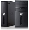
power button 9. optical drive 2. Front And Back View 1. optical drive bay 6. hard-drive activity light Regulatory Model: D11M Regulatory Type: D11M002 2012 - 04 Front and Back View Figure 1. microphone and headphone connectors 7. Dell Vostro 270 Setup And Features Information About Warnings WARNING: A WARNING indicates a potential for property damage, personal injury, or death. media-card reader status light 3. 19-in-1 media-card reader (optional) 4. optical drive eject button 5. USB 2.0 connectors (2) 8.
power button 9. optical drive 2. Front And Back View 1. optical drive bay 6. hard-drive activity light Regulatory Model: D11M Regulatory Type: D11M002 2012 - 04 Front and Back View Figure 1. microphone and headphone connectors 7. Dell Vostro 270 Setup And Features Information About Warnings WARNING: A WARNING indicates a potential for property damage, personal injury, or death. media-card reader status light 3. 19-in-1 media-card reader (optional) 4. optical drive eject button 5. USB 2.0 connectors (2) 8.
Page 2
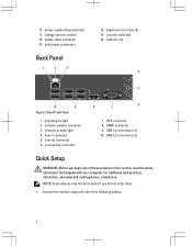
... monitor using only one of the procedures in connector 5. 10. link-integrity light 2. network-activity light 4. microphone connector 7. For additional best practices information, see www.dell.com/regulatory_compliance NOTE: Some devices may not be included if you begin any of the following cables: 2 security cable slot 16. padlock ring Figure 2. network...
... monitor using only one of the procedures in connector 5. 10. link-integrity light 2. network-activity light 4. microphone connector 7. For additional best practices information, see www.dell.com/regulatory_compliance NOTE: Some devices may not be included if you begin any of the following cables: 2 security cable slot 16. padlock ring Figure 2. network...

Page 3
USB Connection 3. Figure 6. Connect the network cable (optional). Connect the USB keyboard or mouse (optional). Figure 7. Network Connection 3 HDMI Connector Figure 4. Figure 3. DVI Connector (optional) 2. VGA Connector Figure 5.
USB Connection 3. Figure 6. Connect the network cable (optional). Connect the USB keyboard or mouse (optional). Figure 7. Network Connection 3 HDMI Connector Figure 4. Figure 3. DVI Connector (optional) 2. VGA Connector Figure 5.

Page 4
Press the power buttons on the monitor and the computer. 4. Figure 8. The following specifications are only those required by law to 240 V 3 V, CR2032 lithium coin cell NOTE: Heat dissipation is calculated by region. Figure 9. Power Wattage Voltage (see the safety information that shipped with your computer for important voltage-setting information) Coin-cell battery 300 W 100 V to 127 V / 200 V to ship with your computer. Connect the power cable(s). Connecting Power 5. Turning On Power Specifications NOTE: Offerings may vary by using the power supply wattage ...
Press the power buttons on the monitor and the computer. 4. Figure 8. The following specifications are only those required by law to 240 V 3 V, CR2032 lithium coin cell NOTE: Heat dissipation is calculated by region. Figure 9. Power Wattage Voltage (see the safety information that shipped with your computer for important voltage-setting information) Coin-cell battery 300 W 100 V to 127 V / 200 V to ship with your computer. Connect the power cable(s). Connecting Power 5. Turning On Power Specifications NOTE: Offerings may vary by using the power supply wattage ...

Page 5
... Conditions (U.S. Information para NOM (únicamente para México) The following information is available at www.dell.com/regulatory_compliance for more information on: • Safety best practices • Regulatory certification • Ergonomics See www.dell.com for additional information on the device described in this document in compliance with your computer and...
... Conditions (U.S. Information para NOM (únicamente para México) The following information is available at www.dell.com/regulatory_compliance for more information on: • Safety best practices • Regulatory certification • Ergonomics See www.dell.com for additional information on the device described in this document in compliance with your computer and...
Page 6
... Windows Vista start button, and Office Outlook® are trademarks of Dell Inc. Other trademarks and trade names may be used in this text: Dell™, the DELL logo, Dell Precision™, Precision ON™, ExpressCharge™, Latitude™, Latitude ON™, OptiPlex™, Vostro™, and Wi-Fi Catcher™ are either the entities...
... Windows Vista start button, and Office Outlook® are trademarks of Dell Inc. Other trademarks and trade names may be used in this text: Dell™, the DELL logo, Dell Precision™, Precision ON™, ExpressCharge™, Latitude™, Latitude ON™, OptiPlex™, Vostro™, and Wi-Fi Catcher™ are either the entities...

Owner's Manual
Page 2
...AMD Phenom™, AMD Sempron™, AMD Athlon™, ATI Radeon™, and ATI FirePro™ are registered trademarks or trademarks of Dell Inc. is a registered trademark of Advanced Micro Devices, Inc. Wi-Fi® is under license. Trademarks used in the U.S. Microsoft&#..., and Office Outlook® are trademarks of Intel Corporation in this text: Dell™, the DELL logo, Dell Precision™, Precision ON™,ExpressCharge™, Latitude™, Latitude ON™, OptiPlex™, Vostro™, and Wi-Fi Catcher™ are either potential damage to avoid the...
...AMD Phenom™, AMD Sempron™, AMD Athlon™, ATI Radeon™, and ATI FirePro™ are registered trademarks or trademarks of Dell Inc. is a registered trademark of Advanced Micro Devices, Inc. Wi-Fi® is under license. Trademarks used in the U.S. Microsoft&#..., and Office Outlook® are trademarks of Intel Corporation in this text: Dell™, the DELL logo, Dell Precision™, Precision ON™,ExpressCharge™, Latitude™, Latitude ON™, OptiPlex™, Vostro™, and Wi-Fi Catcher™ are either potential damage to avoid the...
Owner's Manual
Page 3
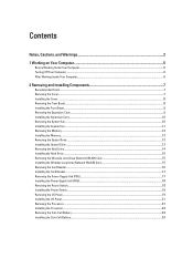
Contents Notes, Cautions, and Warnings 2 1 Working on Your Computer...5 Before Working Inside Your Computer...5 Turning Off Your Computer...6 After Working Inside Your Computer...6 2 Removing and Installing Components 7 Recommended Tools...7 Removing the Cover...7 Installing the Cover...8 Removing the Front Bezel...8 Installing the Front Bezel...9 Removing the Expansion Card...9 Installing the Expansion Card...10 Removing the System Fan...10 Installing the System Fan...11 Removing the Memory...12 Installing the Memory...12 Removing the Optical Drive...12 Installing the Optical Drive...13 ...
Contents Notes, Cautions, and Warnings 2 1 Working on Your Computer...5 Before Working Inside Your Computer...5 Turning Off Your Computer...6 After Working Inside Your Computer...6 2 Removing and Installing Components 7 Recommended Tools...7 Removing the Cover...7 Installing the Cover...8 Removing the Front Bezel...8 Installing the Front Bezel...9 Removing the Expansion Card...9 Installing the Expansion Card...10 Removing the System Fan...10 Installing the System Fan...11 Removing the Memory...12 Installing the Memory...12 Removing the Optical Drive...12 Installing the Optical Drive...13 ...

Owner's Manual
Page 4
...) Diagnostics 39 5 Troubleshooting...41 Diagnostic Power LED Codes...41 Diagnostic Beep Codes...42 Diagnostic Error Messages...42 System Error Messages...46 6 Technical Specifications...47 7 Contacting Dell...51
...) Diagnostics 39 5 Troubleshooting...41 Diagnostic Power LED Codes...41 Diagnostic Beep Codes...42 Diagnostic Error Messages...42 System Error Messages...46 6 Technical Specifications...47 7 Contacting Dell...51

Owner's Manual
Page 5
... working inside the computer. 1. Hold a component such as directed by its metal mounting bracket. Ensure that is not authorized by Dell is not covered by periodically touching an unpainted metal surface, such as authorized in reverse order. Damage due to ground the system ... avoid electrostatic discharge, ground yourself by using a wrist grounding strap or by your computer (see the Regulatory Compliance Homepage at www.dell.com/ regulatory_compliance CAUTION: Many repairs may appear differently than shown in on the cable itself. CAUTION: Handle components and cards with ...
... working inside the computer. 1. Hold a component such as directed by its metal mounting bracket. Ensure that is not authorized by Dell is not covered by periodically touching an unpainted metal surface, such as authorized in reverse order. Damage due to ground the system ... avoid electrostatic discharge, ground yourself by using a wrist grounding strap or by your computer (see the Regulatory Compliance Homepage at www.dell.com/ regulatory_compliance CAUTION: Many repairs may appear differently than shown in on the cable itself. CAUTION: Handle components and cards with ...

Owner's Manual
Page 6
... a network cable, first plug the cable into the network device and then plug it into the computer. 2. Connect your computer, ground yourself by running the Dell Diagnostics. 6 CAUTION: Before touching anything inside your computer and all attached devices to their electrical outlets. 4. While you connect any external devices, cards, and cables...
... a network cable, first plug the cable into the network device and then plug it into the computer. 2. Connect your computer, ground yourself by running the Dell Diagnostics. 6 CAUTION: Before touching anything inside your computer and all attached devices to their electrical outlets. 4. While you connect any external devices, cards, and cables...

Owner's Manual
Page 7
Remove the computer cover. 7 Recommended Tools The procedures in Before Working Inside Your Computer. 2. Follow the procedures in this document may require the following tools: • Small flat-blade screwdriver • Phillips screwdriver • Small plastic scribe Removing the Cover 1. Remove the screws that secure the cover to remove or install the components from your computer. 2 Removing and Installing Components This section provides detailed information on how to the computer. 3. Slide the computer cover towards the back of the computer. 4.
Remove the computer cover. 7 Recommended Tools The procedures in Before Working Inside Your Computer. 2. Follow the procedures in this document may require the following tools: • Small flat-blade screwdriver • Phillips screwdriver • Small plastic scribe Removing the Cover 1. Remove the screws that secure the cover to remove or install the components from your computer. 2 Removing and Installing Components This section provides detailed information on how to the computer. 3. Slide the computer cover towards the back of the computer. 4.

Owner's Manual
Page 8
Follow the procedures in Before Working Inside Your Computer. 2. Removing the Front Bezel 1. Follow the procedures in After Working Inside Your Computer. Rotate the bezel away from the computer to the computer. 4. Slide the computer cover towards the front of the bezel from the chassis. 4. Replace the screws that secure the cover to release the hooks on the chassis. 2. Remove the cover. 3. Pry the front bezel-retention clips away from the chassis. 8 Installing the Cover 1. Place the cover on the opposite edge of the computer. 3.
Follow the procedures in Before Working Inside Your Computer. 2. Removing the Front Bezel 1. Follow the procedures in After Working Inside Your Computer. Rotate the bezel away from the computer to the computer. 4. Slide the computer cover towards the front of the bezel from the chassis. 4. Replace the screws that secure the cover to release the hooks on the chassis. 2. Remove the cover. 3. Pry the front bezel-retention clips away from the chassis. 8 Installing the Cover 1. Place the cover on the opposite edge of the computer. 3.

Owner's Manual
Page 9
Replace the cover. 5. Follow the procedures in Before Working Inside Your Computer. 2. Follow the procedures in After Working Inside Your Computer. Remove the cover. 3. Rotate the front bezel towards the computer. 3. Press on the card-retention latch. 4. Press the release tab on the release-lever to release the securing tab from the notch in the computer. 2. Removing the Expansion Card 1. Press the front bezel till the tabs snap into place. 4. Installing the Front Bezel 1. Place the hooks on the notches in the card. 9
Replace the cover. 5. Follow the procedures in Before Working Inside Your Computer. 2. Follow the procedures in After Working Inside Your Computer. Remove the cover. 3. Rotate the front bezel towards the computer. 3. Press on the card-retention latch. 4. Press the release tab on the release-lever to release the securing tab from the notch in the computer. 2. Removing the Expansion Card 1. Press the front bezel till the tabs snap into place. 4. Installing the Front Bezel 1. Place the hooks on the notches in the card. 9

Owner's Manual
Page 10
Installing the Expansion Card 1. Replace the cover. 4. Place the card into it's socket and press it in the card-retention latch till it snaps into place. 3. Follow the procedures in After Working Inside Your Computer. Remove the cover. 3. Follow the procedures in Before Working Inside Your Computer. 2. Removing the System Fan 1. Secure the expansion card by pushing-in till it snaps into place. 2. Ease the card up and out of its connector and remove it from the system board. 10 Disconnect the fan cable from the computer. 5.
Installing the Expansion Card 1. Replace the cover. 4. Place the card into it's socket and press it in the card-retention latch till it snaps into place. 3. Follow the procedures in After Working Inside Your Computer. Remove the cover. 3. Follow the procedures in Before Working Inside Your Computer. 2. Removing the System Fan 1. Secure the expansion card by pushing-in till it snaps into place. 2. Ease the card up and out of its connector and remove it from the system board. 10 Disconnect the fan cable from the computer. 5.

Owner's Manual
Page 11
Remove the fan from the computer. Place the fan at it's location on the computer. 2. Connect the fan cable to the back of the computer. 5. Replace the cover. 5. 4. Follow the procedures in After Working Inside Your Computer. 11 Replace the screws that secure the fan to the back of the computer. 3. Remove the screws that secure the fan to the system board. 4. Installing the System Fan 1.
Remove the fan from the computer. Place the fan at it's location on the computer. 2. Connect the fan cable to the back of the computer. 5. Replace the cover. 5. 4. Follow the procedures in After Working Inside Your Computer. 11 Replace the screws that secure the fan to the back of the computer. 3. Remove the screws that secure the fan to the system board. 4. Installing the System Fan 1.
Owner's Manual
Page 12
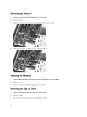
Removing the Optical Drive 1. Disconnect the data cable and power cable from the optical drive. 12 Replace the cover. 3. Press down on the memory-retention tabs on the system board till it snaps into it's connector on each side of the connector on the system board. Follow the procedures in Before Working Inside Your Computer. 2. Follow the procedures in After Working Inside Your Computer. Press the memory module into place. 2. Follow the procedures in Before Working Inside Your Computer. 2. Installing the Memory 1. Lift the memory module out of the memory module. ...
Removing the Optical Drive 1. Disconnect the data cable and power cable from the optical drive. 12 Replace the cover. 3. Press down on the memory-retention tabs on the system board till it snaps into it's connector on each side of the connector on the system board. Follow the procedures in Before Working Inside Your Computer. 2. Follow the procedures in After Working Inside Your Computer. Press the memory module into place. 2. Follow the procedures in Before Working Inside Your Computer. 2. Installing the Memory 1. Lift the memory module out of the memory module. ...

Owner's Manual
Page 13
Remove the screws that secure the optical drive to the computer. 3. Slide the optical drive through the front of the computer. Slide the optical drive through the front of the computer. 2. Follow the procedures in After Working Inside Your Computer. 13 4. Replace the cover. 5. Replace the screws that secure the optical drive to the optical drive. 4. Connect the data cable and power cable to the computer. 5. Installing the Optical Drive 1.
Remove the screws that secure the optical drive to the computer. 3. Slide the optical drive through the front of the computer. Slide the optical drive through the front of the computer. 2. Follow the procedures in After Working Inside Your Computer. 13 4. Replace the cover. 5. Replace the screws that secure the optical drive to the optical drive. 4. Connect the data cable and power cable to the computer. 5. Installing the Optical Drive 1.
Owner's Manual
Page 14
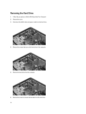
Disconnect the SATA cable and power cable from the computer. 6. Remove the hard drive from the hard drive. 4. Remove the screw to the computer. 5. Remove the cover. 3. Remove the screws that secure the hard drive to release the brackets from the hard drive. 14 Removing the Hard Drive 1. Follow the procedures in Before Working Inside Your Computer. 2.
Disconnect the SATA cable and power cable from the computer. 6. Remove the hard drive from the hard drive. 4. Remove the screw to the computer. 5. Remove the cover. 3. Remove the screws that secure the hard drive to release the brackets from the hard drive. 14 Removing the Hard Drive 1. Follow the procedures in Before Working Inside Your Computer. 2.

Owner's Manual
Page 15
Follow the procedures in , to secure it to the connector. 5. Disconnect the WLAN cables. 4. Replace the cover. 5. Replace the screws that secures the WLAN card to the connector. 2. Place the WLAN card on its connector and push it in Before Working Inside Your Computer. 2. Follow the procedures in After Working Inside Your Computer. Remove the cover. 3. Connect the WLAN cables. 4. Connect the SATA cable and power cable to the hard drive. 2. Follow the procedures in After Working Inside Your Computer. 15 Removing the Wireless Local Area Network (WLAN) Card 1. Installing ...
Follow the procedures in , to secure it to the connector. 5. Disconnect the WLAN cables. 4. Replace the cover. 5. Replace the screws that secures the WLAN card to the connector. 2. Place the WLAN card on its connector and push it in Before Working Inside Your Computer. 2. Follow the procedures in After Working Inside Your Computer. Remove the cover. 3. Connect the WLAN cables. 4. Connect the SATA cable and power cable to the hard drive. 2. Follow the procedures in After Working Inside Your Computer. 15 Removing the Wireless Local Area Network (WLAN) Card 1. Installing ...
