Setup and Quick Reference Guide
Page 1
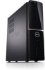
Models: DCSCLF, DCSCMF, DCSCSF www.dell.com | support.dell.com For more information about your computer. Dell™ Vostro™ 420/220/220s Setup and Quick Reference Guide This guide provides a features overview, specifications, and quick setup, software, and troubleshooting information for your operating system, devices, and technologies, see the Dell Technology Guide at support.dell.com.
Models: DCSCLF, DCSCMF, DCSCSF www.dell.com | support.dell.com For more information about your computer. Dell™ Vostro™ 420/220/220s Setup and Quick Reference Guide This guide provides a features overview, specifications, and quick setup, software, and troubleshooting information for your operating system, devices, and technologies, see the Dell Technology Guide at support.dell.com.
Setup and Quick Reference Guide
Page 4
Vostro 220s Back View 28 Vostro 220s Back Panel Connectors 29 4 Specifications 31 5 Troubleshooting 39 Tools 39 Power Lights 39 Beep Codes 39 Error Messages 41 System Messages 46 Troubleshooting Software and Hardware Problems 47 Dell Diagnostics 48 Troubleshooting Tips 50 Power Problems 50 Memory Problems 51 Lockups and Software Problems 52 Dell Technical Update Service 54 Dell Support Utility 55 6 Reinstalling Software 57 Drivers 57 Identifying Drivers 57 Reinstalling Drivers and Utilities 58 4 Contents
Vostro 220s Back View 28 Vostro 220s Back Panel Connectors 29 4 Specifications 31 5 Troubleshooting 39 Tools 39 Power Lights 39 Beep Codes 39 Error Messages 41 System Messages 46 Troubleshooting Software and Hardware Problems 47 Dell Diagnostics 48 Troubleshooting Tips 50 Power Problems 50 Memory Problems 51 Lockups and Software Problems 52 Dell Technical Update Service 54 Dell Support Utility 55 6 Reinstalling Software 57 Drivers 57 Identifying Drivers 57 Reinstalling Drivers and Utilities 58 4 Contents
Setup and Quick Reference Guide
Page 31
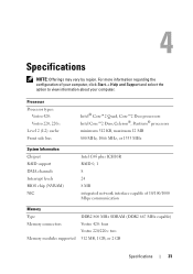
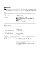
... interface capable of your computer, click Start→ Help and Support and select the option to view information about your computer. For more information regarding the configuration of 10/100/1000 Mbps communication Memory Type Memory connectors Memory modules supported DDR2 800 MHz SDRAM (DDR2 667 MHz capable) Vostro 420: four Vostro 220/220s: two 512 MB, 1 GB...
... interface capable of your computer, click Start→ Help and Support and select the option to view information about your computer. For more information regarding the configuration of 10/100/1000 Mbps communication Memory Type Memory connectors Memory modules supported DDR2 800 MHz SDRAM (DDR2 667 MHz capable) Vostro 420: four Vostro 220/220s: two 512 MB, 1 GB...
Setup and Features Information Tech Sheet
Page 7
...) Vostro 420 - one Vostro 420/220/220s - one Internally accessible: 3.5-inch SATA drive bays Vostro 420 - Specifications NOTE: The following specifications are only those required by law to ship with optional Bluetooth® external USB floppy disk drive Video Type: Integrated Discrete Intel® GMA X4500HD supports dual independent displays NOTE: Support for your computer. two Vostro 220s - up to support.dell...
...) Vostro 420 - one Vostro 420/220/220s - one Internally accessible: 3.5-inch SATA drive bays Vostro 420 - Specifications NOTE: The following specifications are only those required by law to ship with optional Bluetooth® external USB floppy disk drive Video Type: Integrated Discrete Intel® GMA X4500HD supports dual independent displays NOTE: Support for your computer. two Vostro 220s - up to support.dell...
Service Manual
Page 5
... 55 Removing the Chassis Support Bracket 55 Replacing the Chassis Support Bracket 57 6 PCI and PCI Express Cards 59 Removing a PCI or PCI Express Card 59 Installing a PCI or PCI Express Card 60 Configuring Your Computer After Removing or Installing a PCI or PCI Express Card 63 7 Drives 65 Hard Drives 65 Removing a Hard... Reader . . . . 77 Optical Drive 80 Removing an Optical Drive 80 Replacing or Adding an Optical Drive 82 Removing a Drive Bay Break-Away Metal Plate . . . . 85 Vostro 420 and Vostro 220 85 Vostro 220s 86 Contents 5
... 55 Removing the Chassis Support Bracket 55 Replacing the Chassis Support Bracket 57 6 PCI and PCI Express Cards 59 Removing a PCI or PCI Express Card 59 Installing a PCI or PCI Express Card 60 Configuring Your Computer After Removing or Installing a PCI or PCI Express Card 63 7 Drives 65 Hard Drives 65 Removing a Hard... Reader . . . . 77 Optical Drive 80 Removing an Optical Drive 80 Replacing or Adding an Optical Drive 82 Removing a Drive Bay Break-Away Metal Plate . . . . 85 Vostro 420 and Vostro 220 85 Vostro 220s 86 Contents 5
Service Manual
Page 47
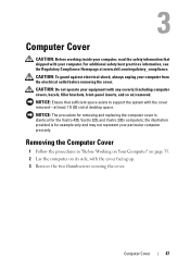
...at www.dell.com/regulatory_compliance. Removing the Computer Cover 1 Follow the procedures in "Before Working on Your Computer" on page 35. 2 Lay the computer on ) removed. CAUTION: Do not operate your equipment with your computer. the...support the system with the cover facing up. 3 Remove the two thumbscrews securing the cover. For additional safety best practices information, see the Regulatory Compliance Homepage at least 1 ft (30 cm) of desktop space. NOTICE: The procedure for removing and replacing the computer cover is for the Vostro 420, Vostro 220, and Vostro 220s computers...
...at www.dell.com/regulatory_compliance. Removing the Computer Cover 1 Follow the procedures in "Before Working on Your Computer" on page 35. 2 Lay the computer on ) removed. CAUTION: Do not operate your equipment with your computer. the...support the system with the cover facing up. 3 Remove the two thumbscrews securing the cover. For additional safety best practices information, see the Regulatory Compliance Homepage at least 1 ft (30 cm) of desktop space. NOTICE: The procedure for removing and replacing the computer cover is for the Vostro 420, Vostro 220, and Vostro 220s computers...
Service Manual
Page 55
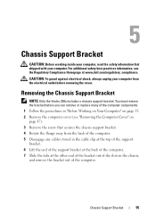
... Vostro 220s includes a chassis support bracket. Chassis Support Bracket 55 CAUTION: To guard against electrical shock, always unplug your computer from the back of the computer. 5 Disengage any cables stored in the cable clip at the top of the support bracket. 6 Lift the end of the support bracket at the back of the computer. 7 Slide the tabs at www.dell...
... Vostro 220s includes a chassis support bracket. Chassis Support Bracket 55 CAUTION: To guard against electrical shock, always unplug your computer from the back of the computer. 5 Disengage any cables stored in the cable clip at the top of the support bracket. 6 Lift the end of the support bracket at the back of the computer. 7 Slide the tabs at www.dell...
Service Manual
Page 59
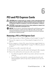
... and PCI Express cards is a Vostro 220s, remove the chassis support bracket (see "Removing the Chassis Support Bracket" on page 55). For additional safety best practices information, see the Regulatory Compliance Homepage at www.dell.com/regulatory_compliance. Otherwise, proceed to step 4. 4 Disconnect any cables connected to the back panel of the computer. 6 Remove the card from...
... and PCI Express cards is a Vostro 220s, remove the chassis support bracket (see "Removing the Chassis Support Bracket" on page 55). For additional safety best practices information, see the Regulatory Compliance Homepage at www.dell.com/regulatory_compliance. Otherwise, proceed to step 4. 4 Disconnect any cables connected to the back panel of the computer. 6 Remove the card from...
Service Manual
Page 60
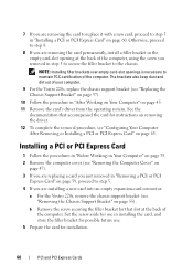
... 5. 4 If you are removing the card permanently, install a filler bracket in the empty card-slot opening at the back of your computer. 9 For the Vostro 220s, replace the chassis support bracket (see "Configuring Your Computer After Removing or Installing a PCI or PCI Express Card" on page 45. 11 Remove the card's driver from the operating...
... 5. 4 If you are removing the card permanently, install a filler bracket in the empty card-slot opening at the back of your computer. 9 For the Vostro 220s, replace the chassis support bracket (see "Configuring Your Computer After Removing or Installing a PCI or PCI Express Card" on page 45. 11 Remove the card's driver from the operating...
Service Manual
Page 62
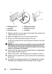
...cards, except for Vostro 220s, which provides a cable clip in the connector and press down firmly. 6 1 5 4 2 3 1 PCI Express x16 card 3 securing tab 5 PCI Express x1 card 2 PCI Express x16 card slot 4 PCI Express x1 card slot 6 securing slot 7 Align the card in a chassis support bracket. See ...Working on Your Computer" on page 63. 62 PCI and PCI Express Cards Ensure that the card is fully seated in the connector slot. 8 Replace and tighten the screw to the equipment. 10 For the Vostro 220s, replace the chassis support bracket (see "Replacing the Chassis Support Bracket" on page...
...cards, except for Vostro 220s, which provides a cable clip in the connector and press down firmly. 6 1 5 4 2 3 1 PCI Express x16 card 3 securing tab 5 PCI Express x1 card 2 PCI Express x16 card slot 4 PCI Express x1 card slot 6 securing slot 7 Align the card in a chassis support bracket. See ...Working on Your Computer" on page 63. 62 PCI and PCI Express Cards Ensure that the card is fully seated in the connector slot. 8 Replace and tighten the screw to the equipment. 10 For the Vostro 220s, replace the chassis support bracket (see "Replacing the Chassis Support Bracket" on page...
Service Manual
Page 65
... shock, always unplug your computer from the electrical outlet before you are for the Vostro 420, Vostro 220, and Vostro 220s computers; Drives 65 For additional safety best practices information, see the Regulatory Compliance Homepage at www.dell.com/regulatory_compliance. the illustrations provided...your computer. Removing a Hard Drive 1 Follow the procedures in "Before Working on Your Computer" on page 35. 2 Remove the computer cover (see "Removing the Computer Cover" on page 47). 3 For the Vostro 220s, remove the chassis support bracket (see "Removing the Chassis Support Bracket...
... shock, always unplug your computer from the electrical outlet before you are for the Vostro 420, Vostro 220, and Vostro 220s computers; Drives 65 For additional safety best practices information, see the Regulatory Compliance Homepage at www.dell.com/regulatory_compliance. the illustrations provided...your computer. Removing a Hard Drive 1 Follow the procedures in "Before Working on Your Computer" on page 35. 2 Remove the computer cover (see "Removing the Computer Cover" on page 47). 3 For the Vostro 220s, remove the chassis support bracket (see "Removing the Chassis Support Bracket...
Service Manual
Page 73
...connected and firmly seated. 9 For the Vostro 220s, replace the chassis support bracket (see "Replacing the Chassis Support Bracket" on page 57). 10 Follow the procedure in "After Working on Your Computer" on page 45. 11 When you restart your computer, check the drive configuration information in ..."Before Working on Your Computer" on page 35. 2 Remove the computer cover (see "Removing the Computer Cover" on page 47). 3 Remove the bezel (see the Regulatory Compliance Homepage at www.dell.com...
...connected and firmly seated. 9 For the Vostro 220s, replace the chassis support bracket (see "Replacing the Chassis Support Bracket" on page 57). 10 Follow the procedure in "After Working on Your Computer" on page 45. 11 When you restart your computer, check the drive configuration information in ..."Before Working on Your Computer" on page 35. 2 Remove the computer cover (see "Removing the Computer Cover" on page 47). 3 Remove the bezel (see the Regulatory Compliance Homepage at www.dell.com...
Service Manual
Page 89
...(s) (if present). CAUTION: To guard against electrical shock, always unplug your computer from the system board. 5 For the Vostro 220s: a Remove the chassis support bracket (see "Removing the Bezel" on page 51). 4 Disconnect the I/O... panel cables from the electrical outlet before removing the cover. b Remove any hard drives from the hard drive cage (see the Regulatory Compliance Homepage at www.dell.com/regulatory_compliance. NOTICE: When sliding the I/O panel out of the computer...
...(s) (if present). CAUTION: To guard against electrical shock, always unplug your computer from the system board. 5 For the Vostro 220s: a Remove the chassis support bracket (see "Removing the Bezel" on page 51). 4 Disconnect the I/O... panel cables from the electrical outlet before removing the cover. b Remove any hard drives from the hard drive cage (see the Regulatory Compliance Homepage at www.dell.com/regulatory_compliance. NOTICE: When sliding the I/O panel out of the computer...
Service Manual
Page 92
5 For the Vostro 220s: a Replace the chassis support bracket (see "Replacing or Adding a Hard Drive" on page 69) that you removed in step 5 of "Removing the I/O Panel" on page 89. 6 Follow the procedure in "After Working on Your Computer" on page 57). b Replace any hard drives in the hard drive cage (see "Replacing the Chassis Support Bracket" on page 45. 92 I/O Panel
5 For the Vostro 220s: a Replace the chassis support bracket (see "Replacing or Adding a Hard Drive" on page 69) that you removed in step 5 of "Removing the I/O Panel" on page 89. 6 Follow the procedure in "After Working on Your Computer" on page 57). b Replace any hard drives in the hard drive cage (see "Replacing the Chassis Support Bracket" on page 45. 92 I/O Panel
Service Manual
Page 107
... the DC power cables from being pinched or crimped. 3 For the Vostro 220s: a Remove the chassis support bracket (see the Regulatory Compliance Homepage at www.dell.com/regulatory_compliance. Power Supply CAUTION: Before working inside your computer, read the safety information that shipped with your computer from the routing clips (if present) on the chassis. 6 Remove the...
... the DC power cables from being pinched or crimped. 3 For the Vostro 220s: a Remove the chassis support bracket (see the Regulatory Compliance Homepage at www.dell.com/regulatory_compliance. Power Supply CAUTION: Before working inside your computer, read the safety information that shipped with your computer from the routing clips (if present) on the chassis. 6 Remove the...
Service Manual
Page 117
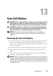
... assistance with the system setup program. 2 Follow the procedures in "Before Working on Your Computer" on page 35. 3 Remove the computer cover (see "Removing the Computer Cover" on page 47). 4 For the Vostro 220s, remove the chassis support bracket (see the Regulatory Compliance Homepage at www.dell.com/regulatory_compliance. Coin-Cell Battery CAUTION: Before working inside your...
... assistance with the system setup program. 2 Follow the procedures in "Before Working on Your Computer" on page 35. 3 Remove the computer cover (see "Removing the Computer Cover" on page 47). 4 For the Vostro 220s, remove the chassis support bracket (see the Regulatory Compliance Homepage at www.dell.com/regulatory_compliance. Coin-Cell Battery CAUTION: Before working inside your...
Service Manual
Page 118
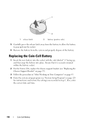
Ensure that it is securely retained within the battery socket. 2 For the Vostro 220s, replace the chassis support bracket (see "Replacing the Chassis Support Bracket" on page 57). 3 Follow the procedure in "After Working on Your Computer" on page 45. 4 Enter the system setup program (see "System Setup Program" on page 129 for instructions) and restore...
Ensure that it is securely retained within the battery socket. 2 For the Vostro 220s, replace the chassis support bracket (see "Replacing the Chassis Support Bracket" on page 57). 3 Follow the procedure in "After Working on Your Computer" on page 45. 4 Enter the system setup program (see "System Setup Program" on page 129 for instructions) and restore...
Service Manual
Page 119
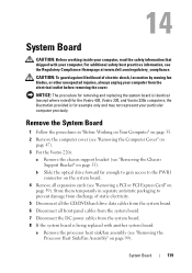
For additional safety best practices information, see the Regulatory Compliance Homepage at www.dell.com/regulatory_compliance. Remove the System Board 1 Follow the procedures in separate antistatic packaging to the PWR1 connector on the system board. 4...before removing the cover. Store them temporarily in "Before Working on Your Computer" on page 35. 2 Remove the computer cover (see "Removing the Computer Cover" on page 47). 3 For the Vostro 220s: a Remove the chassis support bracket (see "Removing the Chassis Support Bracket" on page 55). System Board 119 System Board CAUTION: Before...
For additional safety best practices information, see the Regulatory Compliance Homepage at www.dell.com/regulatory_compliance. Remove the System Board 1 Follow the procedures in separate antistatic packaging to the PWR1 connector on the system board. 4...before removing the cover. Store them temporarily in "Before Working on Your Computer" on page 35. 2 Remove the computer cover (see "Removing the Computer Cover" on page 47). 3 For the Vostro 220s: a Remove the chassis support bracket (see "Removing the Chassis Support Bracket" on page 55). System Board 119 System Board CAUTION: Before...


