User Manual
Page 2
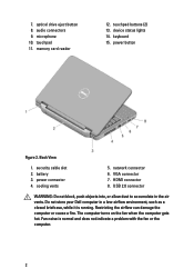
touchpad 11. keyboard 15. power connector 4. USB 2.0 connector WARNING: Do not block, push objects into, or allow dust to accumulate in a low-airflow environment, such as a closed briefcase, while ... or the computer. 2 power button Figure 2. HDMI connector 8. The computer turns on the fan when the computer gets hot. network connector 6. Do not store your Dell computer in the air vents. device status lights 14. security cable slot 2. Restricting the airflow can damage the computer or cause a fire. microphone 10. cooling...
touchpad 11. keyboard 15. power connector 4. USB 2.0 connector WARNING: Do not block, push objects into, or allow dust to accumulate in a low-airflow environment, such as a closed briefcase, while ... or the computer. 2 power button Figure 2. HDMI connector 8. The computer turns on the fan when the computer gets hot. network connector 6. Do not store your Dell computer in the air vents. device status lights 14. security cable slot 2. Restricting the airflow can damage the computer or cause a fire. microphone 10. cooling...
Owners Manual
Page 3
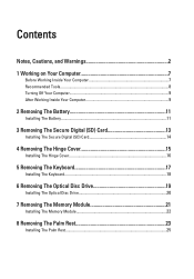
... The Battery 11 Installing The Battery...11 3 Removing The Secure Digital (SD) Card 13 Installing The Secure Digital (SD) Card 14 4 Removing The Hinge Cover 15 Installing The Hinge Cover 16 5 Removing The Keyboard 17 Installing The Keyboard 18 6 Removing The Optical Disc Drive 19 Installing The Optical Disc Drive 20...
... The Battery 11 Installing The Battery...11 3 Removing The Secure Digital (SD) Card 13 Installing The Secure Digital (SD) Card 14 4 Removing The Hinge Cover 15 Installing The Hinge Cover 16 5 Removing The Keyboard 17 Installing The Keyboard 18 6 Removing The Optical Disc Drive 19 Installing The Optical Disc Drive 20...
Owners Manual
Page 4
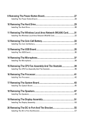
... The Coin-Cell Battery 34 13 Removing The USB Board 35 Installing The USB Board 36 14 Removing The Microphone 37 Installing The Microphone 38 15 Removing The CPU Fan Assembly And The Heatsink 39 Installing The CPU Fan Assembly And The Heatsink 40 16 Removing The Processor 41 Installing The...
... The Coin-Cell Battery 34 13 Removing The USB Board 35 Installing The USB Board 36 14 Removing The Microphone 37 Installing The Microphone 38 15 Removing The CPU Fan Assembly And The Heatsink 39 Installing The CPU Fan Assembly And The Heatsink 40 16 Removing The Processor 41 Installing The...
Owners Manual
Page 15
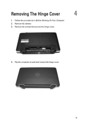
Flip the computer around and remove the hinge cover. 15 Removing The Hinge Cover 4 1. Remove the screws that secure the hinge cover. 4. Remove the battery. 3. Follow the procedures in Before Working On Your Computer. 2.
Flip the computer around and remove the hinge cover. 15 Removing The Hinge Cover 4 1. Remove the screws that secure the hinge cover. 4. Remove the battery. 3. Follow the procedures in Before Working On Your Computer. 2.
Owners Manual
Page 39
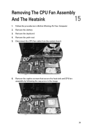
Remove the keyboard. 4. Disconnect the CPU fan cable from the system board. 6. Remove the captive screws that secure the heat sink and CPU fan assembly by following the sequence in Before Working On Your Computer. 2. Removing The CPU Fan Assembly And The Heatsink 15 1. Remove the palm rest. 5. Remove the battery. 3. Follow the procedures in the image. 39
Remove the keyboard. 4. Disconnect the CPU fan cable from the system board. 6. Remove the captive screws that secure the heat sink and CPU fan assembly by following the sequence in Before Working On Your Computer. 2. Removing The CPU Fan Assembly And The Heatsink 15 1. Remove the palm rest. 5. Remove the battery. 3. Follow the procedures in the image. 39
Owners Manual
Page 48
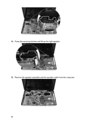
Press the securing latches and lift up the right speaker. 15. 14. Remove the speaker assembly and the speaker cable from the computer. 48
Press the securing latches and lift up the right speaker. 15. 14. Remove the speaker assembly and the speaker cable from the computer. 48
Owners Manual
Page 81
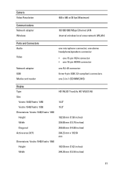
...x 193.54 mm 193.50 mm (7.62 inches) 344.20 mm (13.55 inches) 81 one stereo headphone/speakers connector • one 15-pin VGA connector • one 19-pin HDMI connector one RJ-45 connector three 4-pin USB 2.0-compliant connectors one microphone connector; Camera Video ... (WLAN) Ports and Connectors Audio Video Network adapter USB Media card reader one 3-in-1 (SD/MMC/MS) Display Type Size Vostro 1440/Vostro 1450 Vostro 1540/Vostro 1550 Dimensions: Vostro 1440/Vostro 1450 Height Width Diagonal Active area (X/Y) Dimensions: Vostro 1540/Vostro 1550 Height Width HD WLED TrueLife;
...x 193.54 mm 193.50 mm (7.62 inches) 344.20 mm (13.55 inches) 81 one stereo headphone/speakers connector • one 15-pin VGA connector • one 19-pin HDMI connector one RJ-45 connector three 4-pin USB 2.0-compliant connectors one microphone connector; Camera Video ... (WLAN) Ports and Connectors Audio Video Network adapter USB Media card reader one 3-in-1 (SD/MMC/MS) Display Type Size Vostro 1440/Vostro 1450 Vostro 1540/Vostro 1550 Dimensions: Vostro 1440/Vostro 1450 Height Width Diagonal Active area (X/Y) Dimensions: Vostro 1540/Vostro 1550 Height Width HD WLED TrueLife;

Owners Manual
Page 82
... Vertical Pixel pitch Keyboard Number of keys: Touchpad Active Area: X-axis Y-axis Battery Type Dimensions: Height Width Depth Weight Charge time 82 396.24 mm (15.60 inches) 344.23 mm x 193.54 mm 1366 x 768 pixels at 262K colors 220 nits 0° (closed) to 140° 60 Hz 40/40... 15/30 (H/L) 0.23 mm x 0.23 mm United States and Canada: 86 keys, Europe and Brazil: 87 keys, Japan: 90 keys 90.00 mm (3.54 inches) 49....
... Vertical Pixel pitch Keyboard Number of keys: Touchpad Active Area: X-axis Y-axis Battery Type Dimensions: Height Width Depth Weight Charge time 82 396.24 mm (15.60 inches) 344.23 mm x 193.54 mm 1366 x 768 pixels at 262K colors 220 nits 0° (closed) to 140° 60 Hz 40/40... 15/30 (H/L) 0.23 mm x 0.23 mm United States and Canada: 86 keys, Europe and Brazil: 87 keys, Japan: 90 keys 90.00 mm (3.54 inches) 49....
Owners Manual
Page 84
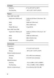
AC Adapter Operating Non-Operating Physical Vostro 1440 / Vostro 1450: Height (with a WLED panel) Width Depth Weight (Minimum) Vostro 1540 / Vostro 1550: Height (with a WLED panel) Width Depth Weight (Minimum) Environmental Temperature: Operating Storage Relative humidity (maximum): Operating Storage Altitude (maximum): Operating Non-... (32 °F to 95 °F) -40 °C to 65 °C (-40 °F to 149 °F) 10 % to 90 % (noncondensing) 5 % to 95 % (noncondensing) -15.2 m to 3048 m (-50 ft to 10,000 ft) -15.2 m to 10,668 m (-50 ft to 35,000 ft) G1 as defined by ISA-71.04-1985 84
AC Adapter Operating Non-Operating Physical Vostro 1440 / Vostro 1450: Height (with a WLED panel) Width Depth Weight (Minimum) Vostro 1540 / Vostro 1550: Height (with a WLED panel) Width Depth Weight (Minimum) Environmental Temperature: Operating Storage Relative humidity (maximum): Operating Storage Altitude (maximum): Operating Non-... (32 °F to 95 °F) -40 °C to 65 °C (-40 °F to 149 °F) 10 % to 90 % (noncondensing) 5 % to 95 % (noncondensing) -15.2 m to 3048 m (-50 ft to 10,000 ft) -15.2 m to 10,668 m (-50 ft to 35,000 ft) G1 as defined by ISA-71.04-1985 84


