Handling swollen Lithium-ion batteries
Page 1
... Release Date: 2020-06-11 Previous Release Version: A04 Like most laptops, Dell laptops use tools of their respective owners. Replace the battery only with a compatible battery purchased from Dell. 1 Document Number: A05 Rev. All rights reserved. Inherent to lithium-ion polymer battery technology is designed to the surface of fire or explosion. or its...
... Release Date: 2020-06-11 Previous Release Version: A04 Like most laptops, Dell laptops use tools of their respective owners. Replace the battery only with a compatible battery purchased from Dell. 1 Document Number: A05 Rev. All rights reserved. Inherent to lithium-ion polymer battery technology is designed to the surface of fire or explosion. or its...

Handling swollen Lithium-ion batteries
Page 2
Frequently Asked Questions. 2 For more information on how to improve the performance and lifespan of the laptop battery and to minimize the possibility of occurrence of charge cycles, or exposure to high heat. Lithium-ion batteries can swell for various reasons such as age, number of the issue, see Dell Laptop Battery -
Frequently Asked Questions. 2 For more information on how to improve the performance and lifespan of the laptop battery and to minimize the possibility of occurrence of charge cycles, or exposure to high heat. Lithium-ion batteries can swell for various reasons such as age, number of the issue, see Dell Laptop Battery -
Vostro 15 - 3568 Quick Start Guide -Windows 10
Page 2
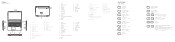
...;叭 12 示燈 13. 觸控墊 14. 喇叭 15. USB 3.0 ポート 16. Power button 6. HDMI port 17. Network port 19. Battery latch 22. USB 2.0 ポート 8 9 10 11 12 13 14 15. Camera 2. Power and battery-status light/ hard-drive activity light 13. Service tag label 1. 摄像...
...;叭 12 示燈 13. 觸控墊 14. 喇叭 15. USB 3.0 ポート 16. Power button 6. HDMI port 17. Network port 19. Battery latch 22. USB 2.0 ポート 8 9 10 11 12 13 14 15. Camera 2. Power and battery-status light/ hard-drive activity light 13. Service tag label 1. 摄像...
Vostro 15-3568 Owners Manual
Page 3
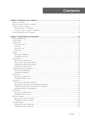
...11 Left view ...12 Palm rest view...13 Right view...13 Battery...14 Removing the battery...14 Installing the battery...14 Optical drive...15 Removing the optical drive ...15 Removing the optical drive bracket...15 Installing the optical drive bracket...16 Installing the optical drive...16 ...WLAN card...24 Memory modules...24 Removing the memory module...24 Installing the memory module...25 Coin-cell battery...26 Removing the coin cell battery...26 Installing the coin cell battery...26 Contents 3 Windows...8 Turning off your - Contents Chapter 1: Working on your computer 7 Safety ...
...11 Left view ...12 Palm rest view...13 Right view...13 Battery...14 Removing the battery...14 Installing the battery...14 Optical drive...15 Removing the optical drive ...15 Removing the optical drive bracket...15 Installing the optical drive bracket...16 Installing the optical drive...16 ...WLAN card...24 Memory modules...24 Removing the memory module...24 Installing the memory module...25 Coin-cell battery...26 Removing the coin cell battery...26 Installing the coin cell battery...26 Contents 3 Windows...8 Turning off your - Contents Chapter 1: Working on your computer 7 Safety ...
Vostro 15-3568 Owners Manual
Page 8
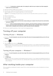
Disconnect all attached devices from their electrical outlets. 7. NOTE: To avoid damaging the system board, you must remove the main battery before you shut down your operating system, press and hold the power button for about 6 seconds to turn them off . CAUTION: ...the computer and all attached devices are turned off your computer and all network cables from the appropriate slots. Disconnect your computer. 1. Remove the main battery. 9. Turning off your computer from the network device. 5. Open the display. 11. Turn the computer top-side up. 10. CAUTION: To ...
Disconnect all attached devices from their electrical outlets. 7. NOTE: To avoid damaging the system board, you must remove the main battery before you shut down your operating system, press and hold the power button for about 6 seconds to turn them off . CAUTION: ...the computer and all attached devices are turned off your computer and all network cables from the appropriate slots. Disconnect your computer. 1. Remove the main battery. 9. Turning off your computer from the network device. 5. Open the display. 11. Turn the computer top-side up. 10. CAUTION: To ...
Vostro 15-3568 Owners Manual
Page 9
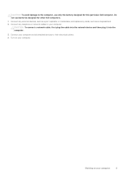
CAUTION: To avoid damage to the computer, use batteries designed for this particular Dell computer. Do not use only the battery designed for other Dell computers. 1. Connect any cards, such as an ExpressCard. 2. Working on your computer. Connect your computer and all attached devices to your computer 9 Turn on your ...
CAUTION: To avoid damage to the computer, use batteries designed for this particular Dell computer. Do not use only the battery designed for other Dell computers. 1. Connect any cards, such as an ExpressCard. 2. Working on your computer. Connect your computer and all attached devices to your computer 9 Turn on your ...
Vostro 15-3568 Owners Manual
Page 10
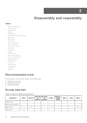
...• Keyboard lattice and Keyboard • Base cover • Hard drive • WLAN card • Memory modules • Coin-cell battery • Power button board • Heat sink • System fan • Speaker • System board • Input-Output board &#...in this document require the following tools: ● Phillips #0 screwdriver ● Phillips #1 screwdriver ● Small plastic scribe Screw size list Table 1. Vostro 15-3562 screw size list Component M2L3 M2L2(Bi M2L2(Bi M2.5L8 g g head07) head05) Optical drive 1 Optical drive bracket 1 Base Cover 8 ...
...• Keyboard lattice and Keyboard • Base cover • Hard drive • WLAN card • Memory modules • Coin-cell battery • Power button board • Heat sink • System fan • Speaker • System board • Input-Output board &#...in this document require the following tools: ● Phillips #0 screwdriver ● Phillips #1 screwdriver ● Small plastic scribe Screw size list Table 1. Vostro 15-3562 screw size list Component M2L3 M2L2(Bi M2L2(Bi M2.5L8 g g head07) head05) Optical drive 1 Optical drive bracket 1 Base Cover 8 ...

Vostro 15-3568 Owners Manual
Page 12
USB 3.1 Gen 1 connector 2. Network connector (No LED indicator) 4. Microphone 5. LCD panel Left view 1. Camera-status light 4. Power and battery-status light/ Hard-drive activity light 2. VGA connector 5. USB 3.1 Gen 1 connector 12 Disassembly and reassembly HDMI 1.4 connector 6. Camera 3. Power connector 3. 1.
USB 3.1 Gen 1 connector 2. Network connector (No LED indicator) 4. Microphone 5. LCD panel Left view 1. Camera-status light 4. Power and battery-status light/ Hard-drive activity light 2. VGA connector 5. USB 3.1 Gen 1 connector 12 Disassembly and reassembly HDMI 1.4 connector 6. Camera 3. Power connector 3. 1.

Vostro 15-3568 Owners Manual
Page 14
To remove the battery: a. Installing the battery 1. Slide the release latch to release the battery [1]. Remove the battery from the computer [2]. 3. Optical drive Removing the battery 1. Insert the battery into the slot and press until it clicks into place. 2. USB 2.0 connector 5. Follow the procedure in After working inside your computer. 2. Security cable slot Battery 4. Follow the procedures in Before working inside your computer. 14 Disassembly and reassembly b.
To remove the battery: a. Installing the battery 1. Slide the release latch to release the battery [1]. Remove the battery from the computer [2]. 3. Optical drive Removing the battery 1. Insert the battery into the slot and press until it clicks into place. 2. USB 2.0 connector 5. Follow the procedure in After working inside your computer. 2. Security cable slot Battery 4. Follow the procedures in Before working inside your computer. 14 Disassembly and reassembly b.

Vostro 15-3568 Owners Manual
Page 15
.... Follow the procedure in Before working inside your computer. 2. To remove the optical drive from the optical drive . Remove the battery. 3. b. Removing the optical drive bracket 1. To remove the optical drive: a. Slide the optical drive out of the arrow indicated on the ...chassis. [2]. b. battery b. Remove the single M2L2(Big head05) screw that secure the optical drive to the computer [1]. Optical drive Removing the optical drive 1. Using...
.... Follow the procedure in Before working inside your computer. 2. To remove the optical drive from the optical drive . Remove the battery. 3. b. Removing the optical drive bracket 1. To remove the optical drive: a. Slide the optical drive out of the arrow indicated on the ...chassis. [2]. b. battery b. Remove the single M2L2(Big head05) screw that secure the optical drive to the computer [1]. Optical drive Removing the optical drive 1. Using...
Vostro 15-3568 Owners Manual
Page 16
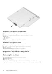
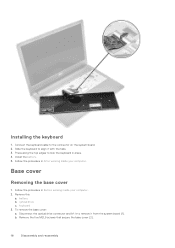
...After working inside your computer. Using a plastic scribe, release the five tabs from the slots located above the keyboard [1]. Install the battery. 4. Installing the optical drive 1. Flip the keyboard on the palm rest to the computer. 3. Install the optical drive bracket. ...procedure in Before working inside your computer. 2. Insert the optical drive into the slot until it clicks into place. 2. Remove the battery. 3. Installing the optical drive bracket 1. Keyboard lattice and Keyboard Removing the keyboard 1. Follow the procedure in After working inside your...
...After working inside your computer. Using a plastic scribe, release the five tabs from the slots located above the keyboard [1]. Install the battery. 4. Installing the optical drive 1. Flip the keyboard on the palm rest to the computer. 3. Install the optical drive bracket. ...procedure in Before working inside your computer. 2. Insert the optical drive into the slot until it clicks into place. 2. Remove the battery. 3. Installing the optical drive bracket 1. Keyboard lattice and Keyboard Removing the keyboard 1. Follow the procedure in After working inside your...
Vostro 15-3568 Owners Manual
Page 18
battery b. Remove the five M2L5 screws that secure the base cover [2]. 18 Disassembly and reassembly Press along the top edges to the connector on the system ... drive connector and lift it to align it from the system board [1]. Slide the keyboard to remove it with the tabs. 3. optical drive c. b. Install the battery. 5. Base cover Removing the base cover 1. Remove the: a. To remove the base cover: a. Follow the procedure in place. 4. Installing the keyboard 1. Connect the keyboard cable...
battery b. Remove the five M2L5 screws that secure the base cover [2]. 18 Disassembly and reassembly Press along the top edges to the connector on the system ... drive connector and lift it to align it from the system board [1]. Slide the keyboard to remove it with the tabs. 3. optical drive c. b. Install the battery. 5. Base cover Removing the base cover 1. Remove the: a. To remove the base cover: a. Follow the procedure in place. 4. Installing the keyboard 1. Connect the keyboard cable...
Vostro 15-3568 Owners Manual
Page 21
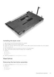
... it clicks into place. 3. M2L2) screws to secure the base cover to the palm rest. 7. keyboard Disassembly and reassembly 21 optical drive c. battery b. Remove the: a. M2.5L8; 3 screws - Hard drive Removing the hard drive assembly 1. Follow the procedure in After working inside your computer.... 2. Align the base cover with the screw holders on the computer. 2. battery 8. M2L2; 2 screws- Flip the computer over. 5. Open the display and connect the optical drive connector to the system board. 6. optical drive c....
... it clicks into place. 3. M2L2) screws to secure the base cover to the palm rest. 7. keyboard Disassembly and reassembly 21 optical drive c. battery b. Remove the: a. M2.5L8; 3 screws - Hard drive Removing the hard drive assembly 1. Follow the procedure in After working inside your computer.... 2. Align the base cover with the screw holders on the computer. 2. battery 8. M2L2; 2 screws- Flip the computer over. 5. Open the display and connect the optical drive connector to the system board. 6. optical drive c....
Vostro 15-3568 Owners Manual
Page 22
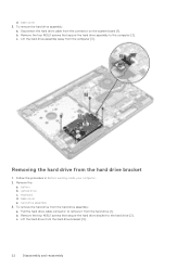
... hard drive [2]. Disconnect the hard drive cable from the hard drive assembly: a. b. Removing the hard drive from the hard drive bracket [3]. 22 Disassembly and reassembly battery b. keyboard d. Lift the hard drive from the hard drive bracket 1. b. c. Pull the hard drive cable connector to remove it from the computer [3]. hard drive assembly...
... hard drive [2]. Disconnect the hard drive cable from the hard drive assembly: a. b. Removing the hard drive from the hard drive bracket [3]. 22 Disassembly and reassembly battery b. keyboard d. Lift the hard drive from the hard drive bracket 1. b. c. Pull the hard drive cable connector to remove it from the computer [3]. hard drive assembly...
Vostro 15-3568 Owners Manual
Page 23
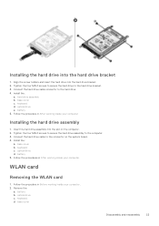
... M2L3 screws to secure the hard drive assembly to the hard drive. 4. optical drive d. Follow the procedures in After working inside your computer. 2. battery b. Connect the hard drive cable connector to the computer. 3. Install the: a. keyboard d. optical drive e. Insert the hard drive assembly into the ...base cover b. optical drive c. Tighten the four M3L3 screws to secure the hard drive to the connector on the computer. 2. battery 5. keyboard c. Align the screw holders and insert the hard drive into the hard drive bracket. 2. WLAN card Removing the WLAN card 1.
... M2L3 screws to secure the hard drive assembly to the hard drive. 4. optical drive d. Follow the procedures in After working inside your computer. 2. battery b. Connect the hard drive cable connector to the computer. 3. Install the: a. keyboard d. optical drive e. Insert the hard drive assembly into the ...base cover b. optical drive c. Tighten the four M3L3 screws to secure the hard drive to the connector on the computer. 2. battery 5. keyboard c. Align the screw holders and insert the hard drive into the hard drive bracket. 2. WLAN card Removing the WLAN card 1.
Vostro 15-3568 Owners Manual
Page 24
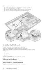
... card from the connectors on the WLAN card. 3. Place the securing tab on the WLAN card and tighten the M2L3 screw on the system board [4]. battery 5. Installing the WLAN card 1. Connect the WLAN cables to the connectors on the WLAN card [3]. base cover b. optical drive d. Disconnect the WLAN cables from the...
... card from the connectors on the WLAN card. 3. Place the securing tab on the WLAN card and tighten the M2L3 screw on the system board [4]. battery 5. Installing the WLAN card 1. Connect the WLAN cables to the connectors on the WLAN card [3]. base cover b. optical drive d. Disconnect the WLAN cables from the...
Vostro 15-3568 Owners Manual
Page 25
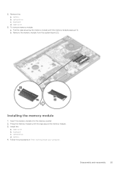
keyboard d. b. Insert the memory module into the memory socket. 2. Install the: a. keyboard c. battery 4. Installing the memory module 1. optical drive d. Follow the procedures in After working inside your computer. base cover b. Remove the: a. base cover 3. optical drive c. Pull the clips securing the memory module until the clips secure the memory module. 3. battery b. Disassembly and reassembly 25 2. Press the memory module until the memory module pops up [1]. To remove memory module: a. Remove the memory module from the system board [2].
keyboard d. b. Insert the memory module into the memory socket. 2. Install the: a. keyboard c. battery 4. Installing the memory module 1. optical drive d. Follow the procedures in After working inside your computer. base cover b. Remove the: a. base cover 3. optical drive c. Pull the clips securing the memory module until the clips secure the memory module. 3. battery b. Disassembly and reassembly 25 2. Press the memory module until the memory module pops up [1]. To remove memory module: a. Remove the memory module from the system board [2].
Vostro 15-3568 Owners Manual
Page 26
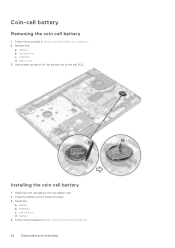
base cover 3. battery b. Use a plastic scribe to lift the battery out of the slot [1,2]. Follow the procedures in Before working inside your computer. 26 Disassembly and reassembly Follow the procedure in After working inside your computer. 2. Insert the coin cell battery into place. 3. keyboard c. optical drive d. optical drive c. Installing the coin cell battery 1. battery b. Remove the: a. keyboard d. Install the: a. Press the battery until it clicks into the battery slot. 2. Coin-cell battery Removing the coin cell battery 1. battery 4.
base cover 3. battery b. Use a plastic scribe to lift the battery out of the slot [1,2]. Follow the procedures in Before working inside your computer. 26 Disassembly and reassembly Follow the procedure in After working inside your computer. 2. Insert the coin cell battery into place. 3. keyboard c. optical drive d. optical drive c. Installing the coin cell battery 1. battery b. Remove the: a. keyboard d. Install the: a. Press the battery until it clicks into the battery slot. 2. Coin-cell battery Removing the coin cell battery 1. battery 4.
Vostro 15-3568 Owners Manual
Page 27
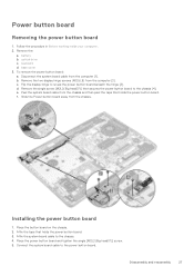
... board cable from the computer [2]. base cover 3. Affix the tape that holds the power button board. Follow the procedure in Before working inside your computer. 2. battery b. Remove the two display hinge screws (M2.5L8) from the chassis and then peel the tape that holds the power button board. 3. Disassembly and reassembly...
... board cable from the computer [2]. base cover 3. Affix the tape that holds the power button board. Follow the procedure in Before working inside your computer. 2. battery b. Remove the two display hinge screws (M2.5L8) from the chassis and then peel the tape that holds the power button board. 3. Disassembly and reassembly...
Vostro 15-3568 Owners Manual
Page 28
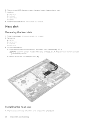
battery b. base cover 3. Tighten the two (M2.5L8) screws to secure the display hinge to the system board [1, 2, 3, 4]. optical drive d. Follow the procedure in Before working ... retention screws and cannot be fully removed. keyboard c. Remove the: a. Loosen the four captive screws that secure the heat sink to the power button board. 7. b. battery 8. Follow the procedures in the order of the callout numbers [1, 2, 3, 4]. Align the screws on the heat sink with the screw holders on the system board...
battery b. base cover 3. Tighten the two (M2.5L8) screws to secure the display hinge to the system board [1, 2, 3, 4]. optical drive d. Follow the procedure in Before working ... retention screws and cannot be fully removed. keyboard c. Remove the: a. Loosen the four captive screws that secure the heat sink to the power button board. 7. b. battery 8. Follow the procedures in the order of the callout numbers [1, 2, 3, 4]. Align the screws on the heat sink with the screw holders on the system board...


