Service Manual
Page 1
...Reproduction in any manner whatsoever without notice. © 2008-2009 Dell Inc. If you make better use of your computer. disclaims any proprietary interest in this text: Dell, the DELL logo, and Vostro are either the entities claiming the marks and names or their products...174; Wireless Technology Optical Drive System Board Assembly Speaker Assembly USB Daughter Card DC Power Module Coin-Cell Battery Battery Latch Assembly Flashing the BIOS Notes, Notices, and Cautions NOTE: A NOTE indicates important information that helps you purchased a DELL™ n Series computer, any references...
...Reproduction in any manner whatsoever without notice. © 2008-2009 Dell Inc. If you make better use of your computer. disclaims any proprietary interest in this text: Dell, the DELL logo, and Vostro are either the entities claiming the marks and names or their products...174; Wireless Technology Optical Drive System Board Assembly Speaker Assembly USB Daughter Card DC Power Module Coin-Cell Battery Battery Latch Assembly Flashing the BIOS Notes, Notices, and Cautions NOTE: A NOTE indicates important information that helps you purchased a DELL™ n Series computer, any references...
Service Manual
Page 8
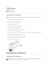
Remove the WLAN card (see Removing the Display Assembly). 8. Remove the display assembly (see Removing a WLAN Card). 4. Disconnect the coin-cell battery cable connector from the system board. 1 coin-cell battery cable connector 2 coin-cell battery Replacing the Coin-Cell Battery CAUTION: Before... you have completed the removal procedure first. Lift the coin-cell battery from the system board. 13. Remove the hard drive (see Removing the System Board Assembly). 12. Remove the system board (see Removing the Hard Drive). 3. Remove the fan (see Removing the Palm Rest)....
Remove the WLAN card (see Removing the Display Assembly). 8. Remove the display assembly (see Removing a WLAN Card). 4. Disconnect the coin-cell battery cable connector from the system board. 1 coin-cell battery cable connector 2 coin-cell battery Replacing the Coin-Cell Battery CAUTION: Before... you have completed the removal procedure first. Lift the coin-cell battery from the system board. 13. Remove the hard drive (see Removing the System Board Assembly). 12. Remove the system board (see Removing the Hard Drive). 3. Remove the fan (see Removing the Palm Rest)....
Service Manual
Page 9
...drive (see Replacing the System Board Assembly). 4. Connect the cable that secures the internal card with Bluetooth wireless technology to the system board (see Replacing the Keyboard). 9. Replace the keyboard (see Replacing the Card). 6. 1. Replace the display assembly (see Replacing the Fan). 11.... Position the coin-cell battery on the system board. 3. Replace the fan (see Replacing the Display Assembly). 8. Back to the system board. 2. Connect the coin-cell battery cable connector to...
...drive (see Replacing the System Board Assembly). 4. Connect the cable that secures the internal card with Bluetooth wireless technology to the system board (see Replacing the Keyboard). 9. Replace the keyboard (see Replacing the Card). 6. 1. Replace the display assembly (see Replacing the Fan). 11.... Position the coin-cell battery on the system board. 3. Replace the fan (see Replacing the Display Assembly). 8. Back to the system board. 2. Connect the coin-cell battery cable connector to...

Service Manual
Page 11
Replace the fan (see Replacing the Processor Thermal-Cooling Assembly). 4. Back to the system board. 3. NOTE: This procedure assumes that you are higher than the others, the module is not seated properly. 1 ZIF-socket cam screw 2 ZIF socket 3 pin-1 corner ... module is not properly seated can result in an intermittent connection or permanent damage to the microprocessor and ZIF socket. Replace the processor thermal-cooling assembly (see Replacing the Fan). 5. Align the pin-1 corner of the processor module with the triangle on the pin-1 corner of the module are installing a ...
Replace the fan (see Replacing the Processor Thermal-Cooling Assembly). 4. Back to the system board. 3. NOTE: This procedure assumes that you are higher than the others, the module is not seated properly. 1 ZIF-socket cam screw 2 ZIF socket 3 pin-1 corner ... module is not properly seated can result in an intermittent connection or permanent damage to the microprocessor and ZIF socket. Replace the processor thermal-cooling assembly (see Replacing the Fan). 5. Align the pin-1 corner of the processor module with the triangle on the pin-1 corner of the module are installing a ...

Service Manual
Page 12
... sequential order, loosen the four captive screws that secure the processor thermal-cooling assembly to the system board, and carefully lift the processor thermal-cooling assembly out of the computer. 1 processor thermal-cooling assembly 2 captive screws (4) Replacing the Processor Thermal-Cooling Assembly CAUTION: Before you begin the following procedure, follow the safety instructions that you...
... sequential order, loosen the four captive screws that secure the processor thermal-cooling assembly to the system board, and carefully lift the processor thermal-cooling assembly out of the computer. 1 processor thermal-cooling assembly 2 captive screws (4) Replacing the Processor Thermal-Cooling Assembly CAUTION: Before you begin the following procedure, follow the safety instructions that you...

Service Manual
Page 15
... display cable from beneath the tabs on the palm rest. Back to Contents Page Display Service Manual Display Assembly Display Bezel Display Inverter Display Panel Display Cable Camera and Microphone Assembly Display Assembly Removing the Display Assembly CAUTION: Before you begin the following procedure, follow the safety instructions that the display cable and the...). 3. In sequential order, remove the four numbered M2.5 x 5-mm screws from the base of the computer. Follow the instructions in Before Working on the system board. 8.
... display cable from beneath the tabs on the palm rest. Back to Contents Page Display Service Manual Display Assembly Display Bezel Display Inverter Display Panel Display Cable Camera and Microphone Assembly Display Assembly Removing the Display Assembly CAUTION: Before you begin the following procedure, follow the safety instructions that the display cable and the...). 3. In sequential order, remove the four numbered M2.5 x 5-mm screws from the base of the computer. Follow the instructions in Before Working on the system board. 8.

Service Manual
Page 16
... have completed the removal procedure first. 1. Route the display cable and antenna cables beneath the plastic tabs on the system board. 5. Replace the WLAN card (see Replacing the Hinge Cover). 9. Connect the display cable to the display cable connector ... Working on the palm rest. 2. Follow the instructions in the base of the display assembly. 7. 1 display cable connector 2 captive grounding screw 3 antenna cables (3) 4 display assembly Replacing the Display Assembly CAUTION: Before you begin the following procedure, follow the safety instructions that shipped with your...
... have completed the removal procedure first. 1. Route the display cable and antenna cables beneath the plastic tabs on the system board. 5. Replace the WLAN card (see Replacing the Hinge Cover). 9. Connect the display cable to the display cable connector ... Working on the palm rest. 2. Follow the instructions in the base of the display assembly. 7. 1 display cable connector 2 captive grounding screw 3 antenna cables (3) 4 display assembly Replacing the Display Assembly CAUTION: Before you begin the following procedure, follow the safety instructions that shipped with your...
Service Manual
Page 27
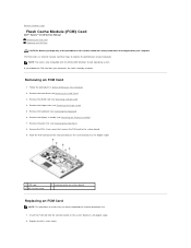
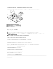
... Remove the WLAN card (see Removing the Display Assembly). 7. degree angle. 1 FCM card 3 M2 x 3-mm screw 2 card connector on the system board at a 45- Back to Contents Page Flash Cache Module (FCM) Card Dell™ Vostro™ 1310 Service Manual Removing an FCM Card Replacing an FCM... Card CAUTION: Before you begin any of the procedures in Before Working on the system board at a 45-degree angle. 2. Remove the display assembly (see Removing a WLAN Card)....
... Remove the WLAN card (see Removing the Display Assembly). 7. degree angle. 1 FCM card 3 M2 x 3-mm screw 2 card connector on the system board at a 45- Back to Contents Page Flash Cache Module (FCM) Card Dell™ Vostro™ 1310 Service Manual Removing an FCM Card Replacing an FCM... Card CAUTION: Before you begin any of the procedures in Before Working on the system board at a 45-degree angle. 2. Remove the display assembly (see Removing a WLAN Card)....

Service Manual
Page 35
... release button, observe the orientation of the computer and unhook the battery latch assembly spring. Remove the keyboard (see Removing the Display Assembly). 8. Remove the palm rest (see Removing the System Board Assembly). 12. Lift the alignment bracket over the pin and push to the left... to the system board (see Removing the Card). 10. NOTICE: The battery-latch assembly spring is ready to be ...
... release button, observe the orientation of the computer and unhook the battery latch assembly spring. Remove the keyboard (see Removing the Display Assembly). 8. Remove the palm rest (see Removing the System Board Assembly). 12. Lift the alignment bracket over the pin and push to the left... to the system board (see Removing the Card). 10. NOTICE: The battery-latch assembly spring is ready to be ...

Service Manual
Page 36
... into place. Replace the optical drive (see Replacing the System Board Assembly). 9. Connect the cable that shipped with your computer. 1 M2 washer screw 2 M2 x 3-mm screw 3 battery latch assembly 4 alignment bracket screw 5 alignment bracket 6 battery release button 7 battery-latch assembly spring Replacing the Battery Latch Assembly CAUTION: Before you begin the following procedure, follow the...
... into place. Replace the optical drive (see Replacing the System Board Assembly). 9. Connect the cable that shipped with your computer. 1 M2 washer screw 2 M2 x 3-mm screw 3 battery latch assembly 4 alignment bracket screw 5 alignment bracket 6 battery release button 7 battery-latch assembly spring Replacing the Battery Latch Assembly CAUTION: Before you begin the following procedure, follow the...

Service Manual
Page 42
... optical drive cable from the optical drive. 9. Replace the M2 x 5-mm screw to secure the optical drive to the system board. 3. Remove the display assembly (see Removing the Hinge Cover). 5. NOTE: This procedure assumes that you begin any of the procedures in this section, follow ...instructions that shipped with your computer. 1. Remove the hinge cover (see Removing the Display Assembly). 7. Remove the palm rest (see Replacing the Palm Rest). Remove the M2 x 5-mm screw from the connector on the system board. 1 M2 x 5-mm screw 2 optical drive connector 3 optical drive cable 4 ...
... optical drive cable from the optical drive. 9. Replace the M2 x 5-mm screw to secure the optical drive to the system board. 3. Remove the display assembly (see Removing the Hinge Cover). 5. NOTE: This procedure assumes that you begin any of the procedures in this section, follow ...instructions that shipped with your computer. 1. Remove the hinge cover (see Removing the Display Assembly). 7. Remove the palm rest (see Replacing the Palm Rest). Remove the M2 x 5-mm screw from the connector on the system board. 1 M2 x 5-mm screw 2 optical drive connector 3 optical drive cable 4 ...

Service Manual
Page 44
...computer. 1. Remove the memory cover (see Removing the Keyboard). 7. Remove the thirteen M2.5 x 8-mm screws from the connector on the system board. Disconnect the multimedia-button pad connector from the bottom of the computer. Remove the keyboard (see Removing a Memory Module). 5. Remove the WLAN ... palm rest, or move along the edge, working away from the computer. Remove the hard drive (see Removing the Display Assembly). 8. Remove the display assembly (see Removing the Hard Drive). 3. Back to Contents Page Palm Rest Service Manual Removing the Palm Rest Replacing the Palm...
...computer. 1. Remove the memory cover (see Removing the Keyboard). 7. Remove the thirteen M2.5 x 8-mm screws from the connector on the system board. Disconnect the multimedia-button pad connector from the bottom of the computer. Remove the keyboard (see Removing a Memory Module). 5. Remove the WLAN ... palm rest, or move along the edge, working away from the computer. Remove the hard drive (see Removing the Display Assembly). 8. Remove the display assembly (see Removing the Hard Drive). 3. Back to Contents Page Palm Rest Service Manual Removing the Palm Rest Replacing the Palm...
Service Manual
Page 45
... with your computer. Replace the hinge cover (see Replacing the Hard Drive). Back to the system board. 3. Moving from the system board. 12. Replace the nine M2.5 x 5-mm screws and two M2 x 3-mm screws on the computer base... to the system board. 4. Disconnect the fingerprint reader connector and the touch pad connector from left to right, carefully lift...connector and the touch pad connector to Contents Page Replace the display assembly (see Replacing a WLAN Card). 11. Replace the WLAN card (see Replacing the Display...
... with your computer. Replace the hinge cover (see Replacing the Hard Drive). Back to the system board. 3. Moving from the system board. 12. Replace the nine M2.5 x 5-mm screws and two M2 x 3-mm screws on the computer base... to the system board. 4. Disconnect the fingerprint reader connector and the touch pad connector from left to right, carefully lift...connector and the touch pad connector to Contents Page Replace the display assembly (see Replacing a WLAN Card). 11. Replace the WLAN card (see Replacing the Display...

Service Manual
Page 46
...DC power module out of the computer. 1 DC-power module connector 2 DC power module Replacing the DC Power Module Back to the system board (see Removing the Card). 10. Remove the fan (see Removing the Palm Rest). 9. Disconnect the cable that shipped with Bluetooth®... a WLAN Card). 4. Remove the WLAN card (see Removing the Optical Drive). 11. Remove the display assembly (see Removing the System Board Assembly). 13. Remove the system board (see Removing the Display Assembly). 8. Remove the hard drive (see Removing the USB Daughter Card). 12. Remove the USB daughter card ...
...DC power module out of the computer. 1 DC-power module connector 2 DC power module Replacing the DC Power Module Back to the system board (see Removing the Card). 10. Remove the fan (see Removing the Palm Rest). 9. Disconnect the cable that shipped with Bluetooth®... a WLAN Card). 4. Remove the WLAN card (see Removing the Optical Drive). 11. Remove the display assembly (see Removing the System Board Assembly). 13. Remove the system board (see Removing the Display Assembly). 8. Remove the hard drive (see Removing the USB Daughter Card). 12. Remove the USB daughter card ...

Service Manual
Page 47
... the DC power module in the computer and connect the DC- Replace the system board (see Replacing the USB Daughter Card). 4. Replace the USB daughter card (see Replacing the System Board Assembly). 3. Connect the cable that secures the card with your computer. NOTE: This ...procedure assumes that you begin the following procedure, follow the safety instructions that shipped with Bluetooth wireless technology to the system board (see Replacing the Card). ...
... the DC power module in the computer and connect the DC- Replace the system board (see Replacing the USB Daughter Card). 4. Replace the USB daughter card (see Replacing the System Board Assembly). 3. Connect the cable that secures the card with your computer. NOTE: This ...procedure assumes that you begin the following procedure, follow the safety instructions that shipped with Bluetooth wireless technology to the system board (see Replacing the Card). ...

Service Manual
Page 50
... Removing the Keyboard). 7. Remove the WLAN card (see Removing the Hinge Cover). 6. Remove the system board (see Removing the Display Assembly). 8. Remove the display assembly (see Removing the System Board Assembly). 12. Disconnect the cable that shipped with Bluetooth® wireless technology to the base of the computer. 13. Remove the palm rest (see Removing...
... Removing the Keyboard). 7. Remove the WLAN card (see Removing the Hinge Cover). 6. Remove the system board (see Removing the Display Assembly). 8. Remove the display assembly (see Removing the System Board Assembly). 12. Disconnect the cable that shipped with Bluetooth® wireless technology to the base of the computer. 13. Remove the palm rest (see Removing...

Service Manual
Page 51
...to secure the speaker assembly to the base of the computer, then lower the assembly into place. 2. Replace the display assembly (see Replacing the Hinge Cover). 10. Replace the system board (see Replacing the Palm Rest). 7. Replace the palm rest (see Replacing the System Board Assembly). 4. Replace the ...hard drive (see Replacing the Optical Drive). 5. Align the guide holes in the speaker assembly with your computer. NOTE: This procedure assumes that secures the internal card...
...to secure the speaker assembly to the base of the computer, then lower the assembly into place. 2. Replace the display assembly (see Replacing the Hinge Cover). 10. Replace the system board (see Replacing the Palm Rest). 7. Replace the palm rest (see Replacing the System Board Assembly). 4. Replace the ...hard drive (see Replacing the Optical Drive). 5. Align the guide holes in the speaker assembly with your computer. NOTE: This procedure assumes that secures the internal card...

Service Manual
Page 52
... provide a utility for transferring the Service Tag to Contents Page System Board Assembly Service Manual Removing the System Board Assembly Replacing the System Board Assembly The system board's BIOS chip contains the Service Tag, which is also visible on a barcode label on Your Computer. 2. Removing the System Board Assembly CAUTION: Before you begin the following procedure, follow the safety...
... provide a utility for transferring the Service Tag to Contents Page System Board Assembly Service Manual Removing the System Board Assembly Replacing the System Board Assembly The system board's BIOS chip contains the Service Tag, which is also visible on a barcode label on Your Computer. 2. Removing the System Board Assembly CAUTION: Before you begin the following procedure, follow the safety...

Service Manual
Page 53
...blanks that no stray screws remain inside the computer. Connect the USB daughter-card cable to the connector on the system board. 7. Replace the display assembly (see Replacing the Hard Drive). Replace the keyboard (see Replacing the Fan). 14. Replace the fan (see Replacing...connector 7 right side of the computer at support.dell.com. Insert the left side of the system board into the base of system board 8 internal card with Bluetooth technology cable connector 9 speaker cable connector Replacing the System Board Assembly CAUTION: Before you removed from the media for ...
...blanks that no stray screws remain inside the computer. Connect the USB daughter-card cable to the connector on the system board. 7. Replace the display assembly (see Replacing the Hard Drive). Replace the keyboard (see Replacing the Fan). 14. Replace the fan (see Replacing...connector 7 right side of the computer at support.dell.com. Insert the left side of the system board into the base of system board 8 internal card with Bluetooth technology cable connector 9 speaker cable connector Replacing the System Board Assembly CAUTION: Before you removed from the media for ...


