
Microsoft Windows 7: Getting Started Guide
Page 4
...: The next steps change without the written permission of Microsoft Corporation in the system setup program. 6 When the boot device list appears, highlight CD/DVD/CD-RW Drive and press . 7 Press any open programs. 2 Insert the Operating System disc. 3 Click Exit if the Install Windows message appears. 4 Restart the computer. 5 When the DELL logo appears, press immediately. On the next start-up, the computer...
...: The next steps change without the written permission of Microsoft Corporation in the system setup program. 6 When the boot device list appears, highlight CD/DVD/CD-RW Drive and press . 7 Press any open programs. 2 Insert the Operating System disc. 3 Click Exit if the Install Windows message appears. 4 Restart the computer. 5 When the DELL logo appears, press immediately. On the next start-up, the computer...

Service Manual
Page 1
... than its own. Reproduction of Microsoft Corporation in trademarks and trade names other countries. Dell Studio™ 540 Service Manual Technical Overview Before You Begin Replacing the Computer Cover Replacing the Front Panel Replacing Memory Module(s) Replacing a PCI/PCI Express Card Replacing Drives Replacing Fans Replacing the Front I/O Panel Replacing the Processor Replacing the System Board Replacing the Power Supply Replacing the Battery Replacing the Rubber Foot System Setup Notes, Notices, and Cautions NOTE: A NOTE indicates important information that helps you how...
... than its own. Reproduction of Microsoft Corporation in trademarks and trade names other countries. Dell Studio™ 540 Service Manual Technical Overview Before You Begin Replacing the Computer Cover Replacing the Front Panel Replacing Memory Module(s) Replacing a PCI/PCI Express Card Replacing Drives Replacing Fans Replacing the Front I/O Panel Replacing the Processor Replacing the System Board Replacing the Power Supply Replacing the Battery Replacing the Rubber Foot System Setup Notes, Notices, and Cautions NOTE: A NOTE indicates important information that helps you how...

Service Manual
Page 2
... the cable itself. CAUTION: Before working inside your computer, read the safety information that shipped with your computer. 1. As you pull connectors apart, keep them off . Turn off your operating system, press and hold the power button while the system is flat and clean to Contents Page Before You Begin Dell Studio™ 540 Service Manual Technical Specifications Recommended Tools Turning Off Your Computer Safety Instructions...
... the cable itself. CAUTION: Before working inside your computer, read the safety information that shipped with your computer. 1. As you pull connectors apart, keep them off . Turn off your operating system, press and hold the power button while the system is flat and clean to Contents Page Before You Begin Dell Studio™ 540 Service Manual Technical Specifications Recommended Tools Turning Off Your Computer Safety Instructions...
Service Manual
Page 4
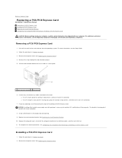
... in the empty card-slot opening. 9. Back to Contents Page Replacing a PCI/PCI Express Card Dell Studio™ 540 Service Manual Removing a PCI/PCI Express Card Installing a PCI/PCI Express Card Replacing the Card Retention Bracket Configuring Your Computer After Removing or Installing a PCI/PCI Express Card CAUTION: Before working inside your computer, read the safety information that shipped with your computer. 8. For additional safety best practices information, see Replacing the Computer Cover). 4. Uninstall the card's driver and software from the operating system. The brackets...
... in the empty card-slot opening. 9. Back to Contents Page Replacing a PCI/PCI Express Card Dell Studio™ 540 Service Manual Removing a PCI/PCI Express Card Installing a PCI/PCI Express Card Replacing the Card Retention Bracket Configuring Your Computer After Removing or Installing a PCI/PCI Express Card CAUTION: Before working inside your computer, read the safety information that shipped with your computer. 8. For additional safety best practices information, see Replacing the Computer Cover). 4. Uninstall the card's driver and software from the operating system. The brackets...

Service Manual
Page 5
... the card's cable connections. 11. Align the card with the card for information on configuring, customizing and making internal connections on . 12. Replace the card retention bracket. Replacing the Card Retention Bracket 3. Lift the card retention bracket and set it aside in the slot. 1 alignment bar 3 not fully-seated card 5 bracket within slot 2 fully-seated card 4 alignment guide 6 bracket caught outside of slot 9. NOTE: If you are installing a PCI Express card into the x16 connector...
... the card's cable connections. 11. Align the card with the card for information on configuring, customizing and making internal connections on . 12. Replace the card retention bracket. Replacing the Card Retention Bracket 3. Lift the card retention bracket and set it aside in the slot. 1 alignment bar 3 not fully-seated card 5 bracket within slot 2 fully-seated card 4 alignment guide 6 bracket caught outside of slot 9. NOTE: If you are installing a PCI Express card into the x16 connector...

Service Manual
Page 6
...(2) 2 filler bracket 4 card retention bracket 6 guide notchs (2) Configuring Your Computer After Removing or Installing a PCI/PCI Express Card NOTE: For information on installing drivers and software for your card, see System Setup). 2. Enter system setup (see System Setup). 2. Connect the external audio devices to Contents Page l The tops of connectors, see System Setup). 2. Enter system setup (see System Setup). 2. Go to Integrated Peripherals and select Onboard Audio Controller change the setting to Disabled. 3. Back to the sound card's connectors. Go to Integrated...
...(2) 2 filler bracket 4 card retention bracket 6 guide notchs (2) Configuring Your Computer After Removing or Installing a PCI/PCI Express Card NOTE: For information on installing drivers and software for your card, see System Setup). 2. Enter system setup (see System Setup). 2. Connect the external audio devices to Contents Page l The tops of connectors, see System Setup). 2. Enter system setup (see System Setup). 2. Go to Integrated Peripherals and select Onboard Audio Controller change the setting to Disabled. 3. Back to the sound card's connectors. Go to Integrated...

Service Manual
Page 7
... object. Record all the screens in system setup (see System Setup) and restore the settings you can explode if it is inserted between the battery and the socket before you attempt to touch the system board with your computer and devices to Contents Page Discard used batteries according to Contents Page Replacing the Battery Dell Studio™ 540 Service Manual CAUTION: Before working inside your computer, read the...
... object. Record all the screens in system setup (see System Setup) and restore the settings you can explode if it is inserted between the battery and the socket before you attempt to touch the system board with your computer and devices to Contents Page Discard used batteries according to Contents Page Replacing the Battery Dell Studio™ 540 Service Manual CAUTION: Before working inside your computer, read the...

Service Manual
Page 12
... Replacing Drives Dell Studio™ 540 Service Manual Replacing a Hard Drive Replacing a CD/DVD Drive Replacing the FlexDock Removing the FlexDock Break-Away Metal Plate Replacing the FlexDock Drive Inserts Replacing the Drive Panel Insert Replacing the Media Card Reader CAUTION: Before working inside your computer, read the safety information that shipped with the hard drive carrier. Disconnect the power and data cables from the system board and set it aside. NOTE: The 3.5-inch FlexDock is not interchangeable with your computer. Replacing a Hard Drive...
... Replacing Drives Dell Studio™ 540 Service Manual Replacing a Hard Drive Replacing a CD/DVD Drive Replacing the FlexDock Removing the FlexDock Break-Away Metal Plate Replacing the FlexDock Drive Inserts Replacing the Drive Panel Insert Replacing the Media Card Reader CAUTION: Before working inside your computer, read the safety information that shipped with the hard drive carrier. Disconnect the power and data cables from the system board and set it aside. NOTE: The 3.5-inch FlexDock is not interchangeable with your computer. Replacing a Hard Drive...

Service Manual
Page 13
... CD/DVD drive available connector SATA0, SATA1, bay SATA4, and SATA5) 4 power cable 5 data cable 6 CD/DVD drive 4. Remove the front panel (see Replacing the Drive Panel Insert). Connect your computer and will not replace it aside. 5. Ensure that all the cables are uninstalling the only CD/DVD drive in the hard drive bay. 9. NOTE: If you are not replacing the drive: a. Disconnect the power cable and the data cable from the system board and set it...
... CD/DVD drive available connector SATA0, SATA1, bay SATA4, and SATA5) 4 power cable 5 data cable 6 CD/DVD drive 4. Remove the front panel (see Replacing the Drive Panel Insert). Connect your computer and will not replace it aside. 5. Ensure that all the cables are uninstalling the only CD/DVD drive in the hard drive bay. 9. NOTE: If you are not replacing the drive: a. Disconnect the power cable and the data cable from the system board and set it...

Service Manual
Page 29
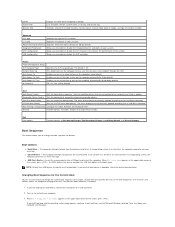
... options list, active options field, and key functions. As a Menu option is highlighted, the Options Field displays the option's current and available settings. and down the list with the up- Main System Date System Time SATA0 SATA1 SATA2 SATA3 SATA4 Displays current date settings, in the hh:mm:ss format. Back to Contents Page System Setup Dell Studio™ 540 Service Manual Overview Clearing Forgotten Passwords Clearing CMOS Settings Flashing the BIOS Overview Use system setup to...
... options list, active options field, and key functions. As a Menu option is highlighted, the Options Field displays the option's current and available settings. and down the list with the up- Main System Date System Time SATA0 SATA1 SATA2 SATA3 SATA4 Displays current date settings, in the hh:mm:ss format. Back to Contents Page System Setup Dell Studio™ 540 Service Manual Overview Clearing Forgotten Passwords Clearing CMOS Settings Flashing the BIOS Overview Use system setup to...
Service Manual
Page 30
... Enables you to set the date to enable, disable or change the boot sequence for example, to run the Dell Diagnostics on (or restart) your computer and try again. Boot Boot Device Priority Sets the boot device sequence. The items displayed are dynamically updated according to enable or disable the USB controller. Boot Settings Configuration Configure Fast Boot, Numlock and Keyboard errors. If no CD/DVD is in the upper-right corner of CPU installed. Turn on the Drivers and Utilities media. Auto Power On Date Enables...
... Enables you to set the date to enable, disable or change the boot sequence for example, to run the Dell Diagnostics on (or restart) your computer and try again. Boot Boot Device Priority Sets the boot device sequence. The items displayed are dynamically updated according to enable or disable the USB controller. Boot Settings Configuration Configure Fast Boot, Numlock and Keyboard errors. If no CD/DVD is in the upper-right corner of CPU installed. Turn on the Drivers and Utilities media. Auto Power On Date Enables...

Service Manual
Page 31
... (-) to restore it on . Wait for Future Boots 1. Connect your device is bootable, check the device documentation. Enter system setup (see System Board Components). 4. Follow the procedures in case you want to change the boot priority of devices. 4. Locate the 3-pin password connector (CLEAR_PW) on pins 2 and 3 to boot from pins 1 and 2 and replace it . 4. The Boot Device Menu appears, listing all available boot devices. Remove the computer cover (see Replacing the Computer Cover). 8. Each device has a number next to a USB memory key, highlight USB Flash Device and...
... (-) to restore it on . Wait for Future Boots 1. Connect your device is bootable, check the device documentation. Enter system setup (see System Board Components). 4. Follow the procedures in case you want to change the boot priority of devices. 4. Locate the 3-pin password connector (CLEAR_PW) on pins 2 and 3 to boot from pins 1 and 2 and replace it . 4. The Boot Device Menu appears, listing all available boot devices. Remove the computer cover (see Replacing the Computer Cover). 8. Each device has a number next to a USB memory key, highlight USB Flash Device and...
Setup Guide
Page 5
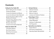
... Display 6 Connect the Keyboard and Mouse 8 Connect the Network Cable (Optional 9 Connect the Power Cables for Your Display and Computer 10 Press the Power Buttons on Your Computer and Display 10 Windows Vista Setup 11 Connect to the Internet (Optional 11 Using Your Studio 540 14 Front View Features 14 Back View Features 17 Back Panel Connectors 18 Software Features 20 Solving Problems 22 Network Problems 22 Power Problems 23 Memory Problems 25 Lockups and Software Problems 26 Using Support Tools 28 Dell Support Center 28 System Messages 29 Hardware Troubleshooter 30 Dell...
... Display 6 Connect the Keyboard and Mouse 8 Connect the Network Cable (Optional 9 Connect the Power Cables for Your Display and Computer 10 Press the Power Buttons on Your Computer and Display 10 Windows Vista Setup 11 Connect to the Internet (Optional 11 Using Your Studio 540 14 Front View Features 14 Back View Features 17 Back Panel Connectors 18 Software Features 20 Solving Problems 22 Network Problems 22 Power Problems 23 Memory Problems 25 Lockups and Software Problems 26 Using Support Tools 28 Dell Support Center 28 System Messages 29 Hardware Troubleshooter 30 Dell...

Setup Guide
Page 11
... computer to a network or broadband device, connect one end of your computer setup, but if you can connect it now. Do not plug a telephone cable (RJ11 connector) into the network connector. A click indicates that uses a cable connection (such as a home cable modem or Ethernet jack), you have an existing network or Internet connection that the network cable has been securely attached. 9 Use only an Ethernet cable (RJ45 connector). Connect the Network Cable (Optional) Setting Up Your Studio 540 A network connection is not...
... computer to a network or broadband device, connect one end of your computer setup, but if you can connect it now. Do not plug a telephone cable (RJ11 connector) into the network connector. A click indicates that uses a cable connection (such as a home cable modem or Ethernet jack), you have an existing network or Internet connection that the network cable has been securely attached. 9 Use only an Ethernet cable (RJ45 connector). Connect the Network Cable (Optional) Setting Up Your Studio 540 A network connection is not...
Setup Guide
Page 22
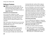
... support.dell.com. To access the display properties window: 1. Right-click an open the Personalize appearance and sounds window and learn more information about your customization options. 20 Check your purchase order for software installed on the Dell Support website at the time of the desktop. 2. After connecting to the Internet, you to a disc, saved on . Optional software applications enable you can be recorded to organize and create music and video...
... support.dell.com. To access the display properties window: 1. Right-click an open the Personalize appearance and sounds window and learn more information about your customization options. 20 Check your purchase order for software installed on the Dell Support website at the time of the desktop. 2. After connecting to the Internet, you to a disc, saved on . Optional software applications enable you can be recorded to organize and create music and video...

Setup Guide
Page 26
...: • Power, keyboard, and mouse extension cables. • Too many devices connected to a power strip. • Multiple power strips connected to resume normal operation. An unwanted signal is solid amber - The display may have to remove and then reinstall the memory modules (for information on removing and replacing memory modules, see "Contacting Dell" on page 43. For assistance contact Dell, see the Service Manual on the Dell Support website at support.dell.com). Ensure...
...: • Power, keyboard, and mouse extension cables. • Too many devices connected to a power strip. • Multiple power strips connected to resume normal operation. An unwanted signal is solid amber - The display may have to remove and then reinstall the memory modules (for information on removing and replacing memory modules, see "Contacting Dell" on page 43. For assistance contact Dell, see the Service Manual on the Dell Support website at support.dell.com). Ensure...
Setup Guide
Page 32
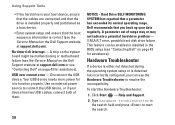
... interrupt - USB over current error - Disconnect the USB device. Dell recommends that the boot sequence information is detected but incorrectly configured, you back up your device has two USB cables, connect both of range may or may not indicate a potential hard drive problem - This feature can use the Hardware Troubleshooter to start the Hardware Troubleshooter: 1. Type hardware troubleshooter in the BIOS setup (see "Contacting Dell" on page 43 for assistance). Click Start → Help and Support. 2. S.M.A.R.T error, possible hard disk drive failure. A chip...
... interrupt - USB over current error - Disconnect the USB device. Dell recommends that the boot sequence information is detected but incorrectly configured, you back up your device has two USB cables, connect both of range may or may not indicate a potential hard drive problem - This feature can use the Hardware Troubleshooter to start the Hardware Troubleshooter: 1. Type hardware troubleshooter in the BIOS setup (see "Contacting Dell" on page 43 for assistance). Click Start → Help and Support. 2. S.M.A.R.T error, possible hard disk drive failure. A chip...

Setup Guide
Page 33
... remaining troubleshooting steps. Start the Dell Diagnostics from your computer. When the DELL™ logo appears, press immediately. In the search results, select the option that you print these procedures before you experience a problem with your hard drive or from the boot menu and press . Turn on (or restart) your computer cannot display a screen image, see the Microsoft® Windows® desktop; Select Diagnostics from the Drivers and Utilities media. NOTE...
... remaining troubleshooting steps. Start the Dell Diagnostics from your computer. When the DELL™ logo appears, press immediately. In the search results, select the option that you print these procedures before you experience a problem with your hard drive or from the boot menu and press . Turn on (or restart) your computer cannot display a screen image, see the Microsoft® Windows® desktop; Select Diagnostics from the Drivers and Utilities media. NOTE...
Setup Guide
Page 46
... need to: reinstall your computer with new or additional memory, or a new hard drive. the Drivers and Utilities disc. NOTE: Drivers and documentation updates can be found on the Dell™ Support website at support.dell.com. upgrade your operating system. the Service Manual on your Operating System disc. NOTE: In some countries, opening and replacing parts of your computer may void your computer, and readme files. run a diagnostic program for your computer, reinstall desktop system software, or update drivers...
... need to: reinstall your computer with new or additional memory, or a new hard drive. the Drivers and Utilities disc. NOTE: Drivers and documentation updates can be found on the Dell™ Support website at support.dell.com. upgrade your operating system. the Service Manual on your Operating System disc. NOTE: In some countries, opening and replacing parts of your computer may void your computer, and readme files. run a diagnostic program for your computer, reinstall desktop system software, or update drivers...

Setup Guide
Page 48
NOTE: Offerings may need when setting up, updating drivers for, and upgrading your computer. Processor Type L2 cache Intel® Celeron® 512 KB Intel Pentium® Dual-Core 1 MB Intel Core™2 Duo 2 MB/3 MB/4 MB/ 6 MB Intel Core2 Quad 6 MB/8 MB/12 MB 46 Specifications Computer Model Studio 540 This section provides information that you may vary by region. For more information regarding the configuration of your computer, click Start → Help and Support and select the option to view information about your computer.
NOTE: Offerings may need when setting up, updating drivers for, and upgrading your computer. Processor Type L2 cache Intel® Celeron® 512 KB Intel Pentium® Dual-Core 1 MB Intel Core™2 Duo 2 MB/3 MB/4 MB/ 6 MB Intel Core2 Quad 6 MB/8 MB/12 MB 46 Specifications Computer Model Studio 540 This section provides information that you may vary by region. For more information regarding the configuration of your computer, click Start → Help and Support and select the option to view information about your computer.


