
Dell Studio 1555 Service Manual
Page 1
...CAUTION: A CAUTION indicates potential damage to change without the written permission of Dell Inc.; All rights reserved. Trademarks used by Bluetooth SIG, Inc. Microsoft, Windows, Windows Vista, and Windows Vista start button logo are not followed. WARNING: A WARNING indicates a potential for property ...United States and/or other than its own. Dell Inc. Dell Studio™ 1555 Service Manual Before You Begin Base Cover Hard Drive Memory Communication Cards Coin-Cell Battery Center Control Cover Keyboard Display Power Button Board Camera (Optional) Palm Rest Speaker Assembly Optical...
...CAUTION: A CAUTION indicates potential damage to change without the written permission of Dell Inc.; All rights reserved. Trademarks used by Bluetooth SIG, Inc. Microsoft, Windows, Windows Vista, and Windows Vista start button logo are not followed. WARNING: A WARNING indicates a potential for property ...United States and/or other than its own. Dell Inc. Dell Studio™ 1555 Service Manual Before You Begin Base Cover Hard Drive Memory Communication Cards Coin-Cell Battery Center Control Cover Keyboard Display Power Button Board Camera (Optional) Palm Rest Speaker Assembly Optical...
Dell Studio 1555 Service Manual
Page 3
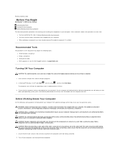
... with your computer. If your computer and attached devices did not automatically turn off your operating system, press and hold the power button for removing and installing the components in this document may require the following safety guidelines to help protect your computer from being ...the connector's pins. 1. l You have already removed the original component, if installed. Back to Contents Page Before You Begin Dell Studio™ 1555 Service Manual Recommended Tools Turning Off Your Computer Before Working Inside Your Computer This document provides procedures for at least 8...
... with your computer. If your computer and attached devices did not automatically turn off your operating system, press and hold the power button for removing and installing the components in this document may require the following safety guidelines to help protect your computer from being ...the connector's pins. 1. l You have already removed the original component, if installed. Back to Contents Page Before You Begin Dell Studio™ 1555 Service Manual Recommended Tools Turning Off Your Computer Before Working Inside Your Computer This document provides procedures for at least 8...
Dell Studio 1555 Service Manual
Page 4
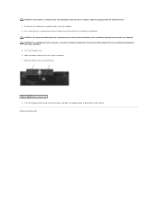
... computer top side up, open the display, and press the power button to the system board, you must remove the battery from the...the ExpressCard slot and the 8-in-1 Memory Card Reader. Do not use only the battery designed for other Dell computers. 5. Slide the battery release latch until it from the network device. 3. Turn the computer over. ...6. Back to the computer, use batteries designed for this particular Dell computer. CAUTION: To disconnect a network cable, first unplug the cable from your computer, and then unplug it clicks ...
... computer top side up, open the display, and press the power button to the system board, you must remove the battery from the...the ExpressCard slot and the 8-in-1 Memory Card Reader. Do not use only the battery designed for other Dell computers. 5. Slide the battery release latch until it from the network device. 3. Turn the computer over. ...6. Back to the computer, use batteries designed for this particular Dell computer. CAUTION: To disconnect a network cable, first unplug the cable from your computer, and then unplug it clicks ...
Dell Studio 1555 Service Manual
Page 16
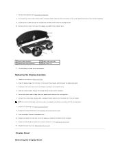
... from their connectors on the system board. Secure the camera cable, display cable, and power button cable to the computer base. 1 camera cable connector 3 power button cable connector 2 display cable connector 4 hinge screws (2) 11. Lift the display assembly out of the computer and then lower... the display into place. 3. Replacing the Display Assembly 1. Connect the camera cable, display cable, and power button cable to their routing guides. 6. Remove the two screws that secure the display assembly to the base of the computer. 11. ...
... from their connectors on the system board. Secure the camera cable, display cable, and power button cable to the computer base. 1 camera cable connector 3 power button cable connector 2 display cable connector 4 hinge screws (2) 11. Lift the display assembly out of the computer and then lower... the display into place. 3. Replacing the Display Assembly 1. Connect the camera cable, display cable, and power button cable to their routing guides. 6. Remove the two screws that secure the display assembly to the base of the computer. 11. ...
Dell Studio 1555 Service Manual
Page 36
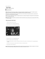
... the base cover (see Removing the Mini-Card). 5. Disconnect the display cable, camera cable, and the power button cable from the bottom of resistance, until the palm rest is not covered by Dell™ is free. CAUTION: To help prevent damage to servicing that shipped with your warranty. CAUTION: Only... Remove the ten screws on the palm rest. Follow the instructions in Before You Begin. 2. Back to Contents Page Palm Rest Dell Studio™ 1555 Service Manual Removing the Palm Rest Replacing the Palm Rest WARNING: Before working inside the computer. For additional safety best...
... the base cover (see Removing the Mini-Card). 5. Disconnect the display cable, camera cable, and the power button cable from the bottom of resistance, until the palm rest is not covered by Dell™ is free. CAUTION: To help prevent damage to servicing that shipped with your warranty. CAUTION: Only... Remove the ten screws on the palm rest. Follow the instructions in Before You Begin. 2. Back to Contents Page Palm Rest Dell Studio™ 1555 Service Manual Removing the Palm Rest Replacing the Palm Rest WARNING: Before working inside the computer. For additional safety best...

Dell Studio 1555 Service Manual
Page 37
...Replacing the Base Cover). Connect the touch pad cable and speaker cable to Contents Page Connect the display cable, camera cable, and power button cable to remove it into place. 2. Replace the base cover (see Replacing the Display Assembly). 5. Replace the eight screws at ...computer. Replace the ten screws on the palm rest. 3. Align the palm rest with the base of the computer. 8. 1 screws (10) 2 power button connector 3 touch pad connector 4 display cable connector 5 camera cable connector 6 speaker connector 9. Slide the antenna cables through their cable routing (see ...
...Replacing the Base Cover). Connect the touch pad cable and speaker cable to Contents Page Connect the display cable, camera cable, and power button cable to remove it into place. 2. Replace the base cover (see Replacing the Display Assembly). 5. Replace the eight screws at ...computer. Replace the ten screws on the palm rest. 3. Align the palm rest with the base of the computer. 8. 1 screws (10) 2 power button connector 3 touch pad connector 4 display cable connector 5 camera cable connector 6 speaker connector 9. Slide the antenna cables through their cable routing (see ...
Dell Studio 1555 Service Manual
Page 38
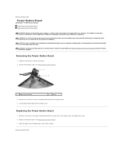
CAUTION: To avoid electrostatic discharge, ground yourself by using a wrist grounding strap or by your computer. Removing the Power Button Board 1. Back to Contents Page Power Button Board Dell Studio™ 1555 Service Manual Removing the Power Button Board Replacing the Power Button Board WARNING: Before working inside your computer. Follow the instructions in place. Replace the display hinges (see the...
CAUTION: To avoid electrostatic discharge, ground yourself by using a wrist grounding strap or by your computer. Removing the Power Button Board 1. Back to Contents Page Power Button Board Dell Studio™ 1555 Service Manual Removing the Power Button Board Replacing the Power Button Board WARNING: Before working inside your computer. Follow the instructions in place. Replace the display hinges (see the...
Setup Guide
Page 5
... 6 Connect the Network Cable (Optional 7 Press the Power Button 8 Set Up Microsoft Windows 9 Create System Recovery Media (Recommended 10 Install the SIM Card (Optional 12 Enable or Disable Wireless (Optional 14 Connect to the Internet (Optional 16 Using Your Studio Laptop 20 Right Side Features 20 Left Side Features 24... Touch Screen (Optional 36 Using the Optical Drive 40 Removing and Replacing the Battery 42 Software Features 44 Free Fall Sensor 45 Dell Dock 46 Dell DataSafe Online Backup 47 Solving Problems 48 Touch Screen Problems 48 Beep Codes 49 Network Problems 50...
... 6 Connect the Network Cable (Optional 7 Press the Power Button 8 Set Up Microsoft Windows 9 Create System Recovery Media (Recommended 10 Install the SIM Card (Optional 12 Enable or Disable Wireless (Optional 14 Connect to the Internet (Optional 16 Using Your Studio Laptop 20 Right Side Features 20 Left Side Features 24... Touch Screen (Optional 36 Using the Optical Drive 40 Removing and Replacing the Battery 42 Software Features 44 Free Fall Sensor 45 Dell Dock 46 Dell DataSafe Online Backup 47 Solving Problems 48 Touch Screen Problems 48 Beep Codes 49 Network Problems 50...
Setup Guide
Page 10
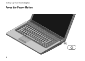
Setting Up Your Studio Laptop Press the Power Button 8
Setting Up Your Studio Laptop Press the Power Button 8
Setup Guide
Page 25
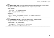
...battery is low. 7 Power button and light - The battery charge is fully charged. The computer is powered by the AC adapter: • Solid white - Turns the computer on steadily or blinks to indicate the battery charge status. The light in the button indicates the following states... light indicates the following power states: • Solid white - the battery: • Off - The computer is turned off or in standby mode. • Off - The battery is adequately charged or the computer is in hibernate state. 23 Using Your Studio Laptop 6 Battery status light...
...battery is low. 7 Power button and light - The battery charge is fully charged. The computer is powered by the AC adapter: • Solid white - Turns the computer on steadily or blinks to indicate the battery charge status. The light in the button indicates the following states... light indicates the following power states: • Solid white - the battery: • Off - The computer is turned off or in standby mode. • Off - The battery is adequately charged or the computer is in hibernate state. 23 Using Your Studio Laptop 6 Battery status light...

Setup Guide
Page 53
.... • Check the AC adapter connections. Solving Problems Power Problems If the power light is not receiving power. • Press the power button. If the power light is solid white and the computer is working by testing it back on. • If the problem persists, contact Dell (see "Contacting Dell" on properly. • Ensure that the light on...
.... • Check the AC adapter connections. Solving Problems Power Problems If the power light is not receiving power. • Press the power button. If the power light is solid white and the computer is working by testing it back on. • If the problem persists, contact Dell (see "Contacting Dell" on properly. • Ensure that the light on...
Setup Guide
Page 54
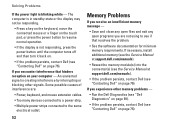
... contact Dell (see "Contacting Dell" on page 76). 52 If you experience other signals. The computer is in standby state or the display may not be responding. • Press a key on the keyboard, move the connected mouse or a finger on the touch pad, or press the power button to the... you encounter interference that resolves the problem. • See the software documentation for minimum memory requirements. Solving Problems If the power light is not responding, press the power button until the computer turns off and then turn it back on. • If the problem persists, contact...
... contact Dell (see "Contacting Dell" on page 76). 52 If you experience other signals. The computer is in standby state or the display may not be responding. • Press a key on the keyboard, move the connected mouse or a finger on the touch pad, or press the power button to the... you encounter interference that resolves the problem. • See the software documentation for minimum memory requirements. Solving Problems If the power light is not responding, press the power button until the computer turns off and then turn it back on. • If the problem persists, contact...

Setup Guide
Page 55
... program: 1. CAUTION: You might lose data if you are unable to 10 seconds until the computer turns off and then restart your mouse, press the power button for an earlier Microsoft® Windows® operating system - If a program crashes repeatedly - Lockups and Software Problems If the computer does not start up - NOTE... the electrical outlet. If a program is designed for at least 8 to perform an operating system shutdown. The Program Compatibility Wizard configures a program so that the power cable is no longer responding 4.
... program: 1. CAUTION: You might lose data if you are unable to 10 seconds until the computer turns off and then restart your mouse, press the power button for an earlier Microsoft® Windows® operating system - If a program crashes repeatedly - Lockups and Software Problems If the computer does not start up - NOTE... the electrical outlet. If a program is designed for at least 8 to perform an operating system shutdown. The Program Compatibility Wizard configures a program so that the power cable is no longer responding 4.


