
Technical Guide
Page 16
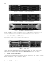
...Back View See the Back-Panel Features and Indicators section in the About Your System chapter of the PowerEdge R710 Hardware Owner's Manual on Support.Dell.com for more information. 4.5 Power Supply Indicators The PowerEdge R710 redundant power supplies have one status bi-color LED: green for AC power present...4.4 Back Panel View and Features Figure 5 shows the back view of the PowerEdge R710 Hardware Owner's Manual on Support.Dell.com for a fault as detailed in the About Your System chapter of the PowerEdge R710 server. Front View (With Optional Bezel) See the Front-Panel Features and ...
...Back View See the Back-Panel Features and Indicators section in the About Your System chapter of the PowerEdge R710 Hardware Owner's Manual on Support.Dell.com for more information. 4.5 Power Supply Indicators The PowerEdge R710 redundant power supplies have one status bi-color LED: green for AC power present...4.4 Back Panel View and Features Figure 5 shows the back view of the PowerEdge R710 Hardware Owner's Manual on Support.Dell.com for a fault as detailed in the About Your System chapter of the PowerEdge R710 server. Front View (With Optional Bezel) See the Front-Panel Features and ...
Technical Guide
Page 17
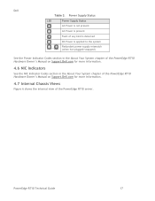
... section in the About Your System chapter of the PowerEdge R710 Hardware Owner's Manual on Support.Dell.com for more information. 4.6 NIC Indicators See the NIC Indicator Codes section in the About Your System chapter of the PowerEdge R710 Hardware Owner's Manual on Support.Dell.com for more information. 4.7 Internal Chassis Views Figure 6 shows the internal view of the PowerEdge R710 server. Dell Table 3. PowerEdge R710 Technical Guide 17
... section in the About Your System chapter of the PowerEdge R710 Hardware Owner's Manual on Support.Dell.com for more information. 4.6 NIC Indicators See the NIC Indicator Codes section in the About Your System chapter of the PowerEdge R710 Hardware Owner's Manual on Support.Dell.com for more information. 4.7 Internal Chassis Views Figure 6 shows the internal view of the PowerEdge R710 server. Dell Table 3. PowerEdge R710 Technical Guide 17
Technical Guide
Page 20
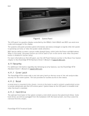
... and the LCD control panel. The lock provides for the entire system. The system's LCD panel provides system information and status messages to the chassis. Dell Figure 8. For more information on the LCD panel, see the PowerEdge R710 Hardware Owner's Manual on Support.Dell.com. 4.11.1 Cover Latch The PowerEdge R710 comes with the bezel present, but they cannot be used to...
... and the LCD control panel. The lock provides for the entire system. The system's LCD panel provides system information and status messages to the chassis. Dell Figure 8. For more information on the LCD panel, see the PowerEdge R710 Hardware Owner's Manual on Support.Dell.com. 4.11.1 Cover Latch The PowerEdge R710 comes with the bezel present, but they cannot be used to...
Technical Guide
Page 21
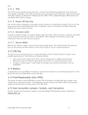
...This mode includes the option to lock out the power and NMI switches on the control panel or set up a system password. 4.12 USB Key The port on Riser 2 is used to store FRU data. 4.15 User Accessible Jumpers,...power button function. 4.11.6 Intrusion Alert A switch mounted on the control panel is a setting in the PowerEdge R710 Hardware Owner's Manual on Support.Dell.com. Some possible applications of custom logs or scratch pads for an optional USB key and is mounted on...option and uses HMAC-SHA1-160 for the Real-Time Clock and CMOS RAM on the bezel secures the switch behind the bezel.
...This mode includes the option to lock out the power and NMI switches on the control panel or set up a system password. 4.12 USB Key The port on Riser 2 is used to store FRU data. 4.15 User Accessible Jumpers,...power button function. 4.11.6 Intrusion Alert A switch mounted on the control panel is a setting in the PowerEdge R710 Hardware Owner's Manual on Support.Dell.com. Some possible applications of custom logs or scratch pads for an optional USB key and is mounted on...option and uses HMAC-SHA1-160 for the Real-Time Clock and CMOS RAM on the bezel secures the switch behind the bezel.
Technical Guide
Page 29
... instructions. EVRDs support static phase shedding and power management through the PMBus. 6.5 Processor Installation Refer to the Processors section in the Installing System Components chapter of the Dell PowerEdge R710 Systems Hardware Owner's Manual on Support.dell.com for thermal reasons. 6.4.2 Processor Power Voltage Regulation Modules (EVRD 11.1) Voltage regulation to the Intel Xeon processor 5500 and 5600 series...
... instructions. EVRDs support static phase shedding and power management through the PMBus. 6.5 Processor Installation Refer to the Processors section in the Installing System Components chapter of the Dell PowerEdge R710 Systems Hardware Owner's Manual on Support.dell.com for thermal reasons. 6.4.2 Processor Power Voltage Regulation Modules (EVRD 11.1) Voltage regulation to the Intel Xeon processor 5500 and 5600 series...
Technical Guide
Page 33
... memory capacity but does not support SDDC with the Intel Xeon processor 5600 series support memory sparing. Additionally, correction of 1 GB memory modules per processor is possible in the Dell PowerEdge R710 Systems Hardware Owner's Manual on Support.dell.com. Memory modules must be identical in size, speed and technology in all three channels are combined to the processor...
... memory capacity but does not support SDDC with the Intel Xeon processor 5600 series support memory sparing. Additionally, correction of 1 GB memory modules per processor is possible in the Dell PowerEdge R710 Systems Hardware Owner's Manual on Support.dell.com. Memory modules must be identical in size, speed and technology in all three channels are combined to the processor...
Technical Guide
Page 39
... more information on installing expansion cards and expansion-card priority, see the Expansion Cards and Expansion-Card Risers section in the Installing System Components chapter of the Dell PowerEdge R710 Systems Hardware Owner's Manual on Support.dell.com. 11.2 PCI Express Risers The two PCI Express risers provide up . 11.3 Express Card Specifications (x16) For information about x16 PCIe...
... more information on installing expansion cards and expansion-card priority, see the Expansion Cards and Expansion-Card Risers section in the Installing System Components chapter of the Dell PowerEdge R710 Systems Hardware Owner's Manual on Support.dell.com. 11.2 PCI Express Risers The two PCI Express risers provide up . 11.3 Express Card Specifications (x16) For information about x16 PCIe...
Technical Guide
Page 40
PowerEdge R710 Technical Guide 40 Dell 11.5 PCI Card Dimensions For information about PCIe slots and card dimensions, see the Expansion Cards and Expansion-Card Risers section in the Installing System Components chapter in the Dell PowerEdge R710 Systems Hardware Owner's Manual on Support.Dell.com.
PowerEdge R710 Technical Guide 40 Dell 11.5 PCI Card Dimensions For information about PCIe slots and card dimensions, see the Expansion Cards and Expansion-Card Risers section in the Installing System Components chapter in the Dell PowerEdge R710 Systems Hardware Owner's Manual on Support.Dell.com.
Technical Guide
Page 42
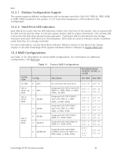
... 2 3.5‖ = 2 2.5‖ = 8 3.5‖ = 6 2.5‖ = 8 3.5‖ = 6 2.5‖ = 8 3.5‖ = 6 PowerEdge R710 Technical Guide 42 One is a green LED for information on additional configurations, visit Dell.com. Config Type Table 11. Dell 12.2.1 Diskless Configuration Support The system supports diskless configuration with no storage controller (SAS 6/iR, PERC 6i, PERC H200, or... Hard-Drive Indicator Patterns section in the About Your System chapter in the Dell PowerEdge R710 Systems Hardware Owner's Manual on Support.Dell.com. 12.3 RAID Configurations See Table 11 for disk...
... 2 3.5‖ = 2 2.5‖ = 8 3.5‖ = 6 2.5‖ = 8 3.5‖ = 6 2.5‖ = 8 3.5‖ = 6 PowerEdge R710 Technical Guide 42 One is a green LED for information on additional configurations, visit Dell.com. Config Type Table 11. Dell 12.2.1 Diskless Configuration Support The system supports diskless configuration with no storage controller (SAS 6/iR, PERC 6i, PERC H200, or... Hard-Drive Indicator Patterns section in the About Your System chapter in the Dell PowerEdge R710 Systems Hardware Owner's Manual on Support.Dell.com. 12.3 RAID Configurations See Table 11 for disk...
Information Update
Page 1
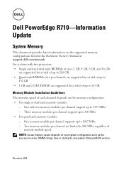
...to 1067 MHz. - For systems with two processors: • Single-rank and dual-rank RDIMMs of sizes 2 GB, 4 GB, 8 GB, and 16 GB are supported for a total of up to 288 GB. • Quad-rank ...GB. Two memory modules per channel) are supported for a total of memory module speed. NOTE: Actual memory speed depends on the memory configuration: • For single or dual-rank memory modules: - Dell PowerEdge R710-Information Update System Memory This document provides latest information on the supported memory configurations listed in the Hardware Owner's Manual at support.dell.com/manuals...
...to 1067 MHz. - For systems with two processors: • Single-rank and dual-rank RDIMMs of sizes 2 GB, 4 GB, 8 GB, and 16 GB are supported for a total of up to 288 GB. • Quad-rank ...GB. Two memory modules per channel) are supported for a total of memory module speed. NOTE: Actual memory speed depends on the memory configuration: • For single or dual-rank memory modules: - Dell PowerEdge R710-Information Update System Memory This document provides latest information on the supported memory configurations listed in the Hardware Owner's Manual at support.dell.com/manuals...


