
Hardware Manual
Page 84
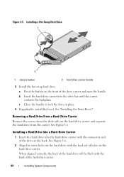
... bay until the carrier contacts the backplane. See "Installing the Front Bezel." Removing a Hard Drive From a Hard-Drive Carrier Remove the screws from the slide rails on the hard-drive carrier and separate the hard drive from the carrier. Figure 3-5.
... bay until the carrier contacts the backplane. See "Installing the Front Bezel." Removing a Hard Drive From a Hard-Drive Carrier Remove the screws from the slide rails on the hard-drive carrier and separate the hard drive from the carrier. Figure 3-5.
Hardware Manual
Page 108
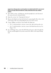
...Opening the System." 3 Remove the blank tray from the flex bay by your warranty. Read and follow the safety instructions that is not authorized by Dell is not covered by squeezing the blue release tabs at the back of the tray and pushing the tray out of the system. 4 Using a ...Phillips screwdriver, disassemble the blank tray: • For 2.5-inch hard-drive systems, remove the slide rails from the tray. • For 3.5-inch hard-drive systems, remove the blank from its electrical outlet. 2 Open the system. See Figure 3-18. 5 For a ...
...Opening the System." 3 Remove the blank tray from the flex bay by your warranty. Read and follow the safety instructions that is not authorized by Dell is not covered by squeezing the blue release tabs at the back of the tray and pushing the tray out of the system. 4 Using a ...Phillips screwdriver, disassemble the blank tray: • For 2.5-inch hard-drive systems, remove the slide rails from the tray. • For 3.5-inch hard-drive systems, remove the blank from its electrical outlet. 2 Open the system. See Figure 3-18. 5 For a ...

Hardware Manual
Page 109
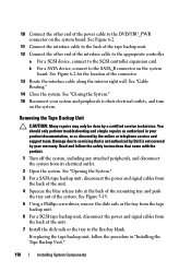
... tape backup unit with the flex bay and slide the unit in HDD Chassis Only) 2 3 1 4 1 drive blank 3 tray 2 screws (4) 4 tape backup unit 6 Install the slide rails or tray on the back of the expansion-card slots. Installing System Components 109 See "Installing an Expansion Card." 9 Connect the power cable to the...
... tape backup unit with the flex bay and slide the unit in HDD Chassis Only) 2 3 1 4 1 drive blank 3 tray 2 screws (4) 4 tape backup unit 6 Install the slide rails or tray on the back of the expansion-card slots. Installing System Components 109 See "Installing an Expansion Card." 9 Connect the power cable to the...
Hardware Manual
Page 110
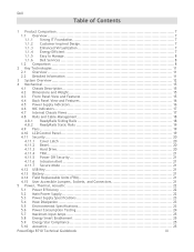
... to the DVD/TBU_PWR connector on the system board. If replacing the tape backup unit, follow the safety instructions that is not authorized by Dell is not covered by your system and peripherals to the flex-bay blank. Damage due to servicing that came with the product. 1 Turn ...See Figure 6-2 for the location of the interface cable to the SCSI controller expansion card. See Figure 3-19. 5 Using a Phillips screwdriver, remove the slide rails or the tray from the tape backup unit. 6 For a SCSI tape backup unit, disconnect the power and signal cables from its electrical outlet. 2 Open the...
... to the DVD/TBU_PWR connector on the system board. If replacing the tape backup unit, follow the safety instructions that is not authorized by Dell is not covered by your system and peripherals to the flex-bay blank. Damage due to servicing that came with the product. 1 Turn ...See Figure 6-2 for the location of the interface cable to the SCSI controller expansion card. See Figure 3-19. 5 Using a Phillips screwdriver, remove the slide rails or the tray from the tape backup unit. 6 For a SCSI tape backup unit, disconnect the power and signal cables from its electrical outlet. 2 Open the...
Technical Guide
Page 3
...IT Foundation 7 1.1.2 Customer-Inspired Design 7 1.1.3 Enhanced Virtualization 7 1.1.4 Energy Efficient 7 1.1.5 Easy to Manage 8 1.1.6 Dell Services 8 1.2 Comparison 8 2 Key Technologies 11 2.1 Overview 11 2.2 Detailed Information 11 3 System Overview 12 4 ...Supply Indicators 16 4.6 NIC Indicators 17 4.7 Internal Chassis Views 17 4.8 Rails and Cable Management 18 4.8.1 ReadyRails Sliding Rails 18 4.8.2 ReadyRails Static Rails 19 4.9 Fans ...19 4.10 LCD Control Panel 19 4.11 Security ... Compliance 25 5.10 Acoustics 25 PowerEdge R710 Technical Guidebook iii
...IT Foundation 7 1.1.2 Customer-Inspired Design 7 1.1.3 Enhanced Virtualization 7 1.1.4 Energy Efficient 7 1.1.5 Easy to Manage 8 1.1.6 Dell Services 8 1.2 Comparison 8 2 Key Technologies 11 2.1 Overview 11 2.2 Detailed Information 11 3 System Overview 12 4 ...Supply Indicators 16 4.6 NIC Indicators 17 4.7 Internal Chassis Views 17 4.8 Rails and Cable Management 18 4.8.1 ReadyRails Sliding Rails 18 4.8.2 ReadyRails Static Rails 19 4.9 Fans ...19 4.10 LCD Control Panel 19 4.11 Security ... Compliance 25 5.10 Acoustics 25 PowerEdge R710 Technical Guidebook iii
Technical Guide
Page 5
...iDRAC, and vFlash 57 Product Safety Certifications 60 Electromagnetic Compatibility Certifications 61 Ergonomics, Acoustics and Hygienics 61 Industry Standards 62 PowerEdge R710 Technical Guidebook v Certifications 60 A.1 Regulatory Certifications 60 A.2 Product Safety Certifications 60 A.3 Electromagnetic Compatibility 61 A.4 Ergonomics, ... Table 12. Table 4. Table 16. Table 11. Table 19. Dell 12.7 External Storage Support 46 13 Video...47 14 Rack Information 48 14.1 Overview 48 14.2 Rails ...48 14.3 Cable Management Arm (CMA 50 14.4 Rack View 50...
...iDRAC, and vFlash 57 Product Safety Certifications 60 Electromagnetic Compatibility Certifications 61 Ergonomics, Acoustics and Hygienics 61 Industry Standards 62 PowerEdge R710 Technical Guidebook v Certifications 60 A.1 Regulatory Certifications 60 A.2 Product Safety Certifications 60 A.3 Electromagnetic Compatibility 61 A.4 Ergonomics, ... Table 12. Table 4. Table 16. Table 11. Table 19. Dell 12.7 External Storage Support 46 13 Video...47 14 Rack Information 48 14.1 Overview 48 14.2 Rails ...48 14.3 Cable Management Arm (CMA 50 14.4 Rack View 50...

Technical Guide
Page 6
... Supplies 23 Memory Channels 31 R710 Sliding Rails with Optional CMA 48 2U Threaded Rack Adapter Brackets Kit 49 R710 Static Rails 49 R710 Mounted in B1 Sliding Rails 51 R710 Mounted in the B1 Sliding Rails with the CMA 51 R710 Mounted in the A2 Static Rails (2-post Center Mount Configuration 52 PowerEdge R710 Technical Guidebook vi Dell Figure 1. Figure 10. Figure...
... Supplies 23 Memory Channels 31 R710 Sliding Rails with Optional CMA 48 2U Threaded Rack Adapter Brackets Kit 49 R710 Static Rails 49 R710 Mounted in B1 Sliding Rails 51 R710 Mounted in the B1 Sliding Rails with the CMA 51 R710 Mounted in the A2 Static Rails (2-post Center Mount Configuration 52 PowerEdge R710 Technical Guidebook vi Dell Figure 1. Figure 10. Figure...
Technical Guide
Page 14
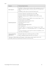
PowerEdge R710 Technical Guide 14 Dell Feature Technical Specification Rack Support ReadyRails™ sliding rails with preloaded material and operating environment and will be less. Featured Database Applications Microsoft® SQL Server® solutions (see Dell.com/SQL) Oracle® database solutions (see Dell.com/Oracle) 1GB means 1 billion bytes and TB equals 1 trillion bytes; actual capacity...
PowerEdge R710 Technical Guide 14 Dell Feature Technical Specification Rack Support ReadyRails™ sliding rails with preloaded material and operating environment and will be less. Featured Database Applications Microsoft® SQL Server® solutions (see Dell.com/SQL) Oracle® database solutions (see Dell.com/Oracle) 1GB means 1 billion bytes and TB equals 1 trillion bytes; actual capacity...
Technical Guide
Page 18
...Cable Management 4.8.1 ReadyRails Sliding Rails ReadyRailsTM Sliding Rails for 4-post racks support the following: Toolless installation in 19‖ EIA-310-E compliant square or unthreaded round hole 4-post racks including all generations of Dell racks Tooled ...installation in 19‖ EIA-310-E compliant threaded hole 4-post racks (requires the 2U Threaded Rack Adapter Brackets Kit) Full extension of the system out of the rack to allow serviceability of key internal components Optional cable management arm (CMA) PowerEdge R710...
...Cable Management 4.8.1 ReadyRails Sliding Rails ReadyRailsTM Sliding Rails for 4-post racks support the following: Toolless installation in 19‖ EIA-310-E compliant square or unthreaded round hole 4-post racks including all generations of Dell racks Tooled ...installation in 19‖ EIA-310-E compliant threaded hole 4-post racks (requires the 2U Threaded Rack Adapter Brackets Kit) Full extension of the system out of the rack to allow serviceability of key internal components Optional cable management arm (CMA) PowerEdge R710...
Technical Guide
Page 19
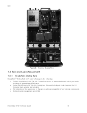
... Toolless installation in 19‖ EIA-310-E compliant square or unthreaded round hole 4-post racks including all generations of Dell racks Tooled installation in the system monitors the speed of the system chassis to provide user access to cool the ...2-post racks See section 14 for more details. 4.9 Fans Five hot-swappable fans are pulse-width modulated fans. See Figure 8. Dell 4.8.2 ReadyRails Static Rails ReadyRailsTM Static Rails for 4-post and 2-post racks support the following features: ACPI-compliant power button with controls: o Two navigation buttons ...
... Toolless installation in 19‖ EIA-310-E compliant square or unthreaded round hole 4-post racks including all generations of Dell racks Tooled installation in the system monitors the speed of the system chassis to provide user access to cool the ...2-post racks See section 14 for more details. 4.9 Fans Five hot-swappable fans are pulse-width modulated fans. See Figure 8. Dell 4.8.2 ReadyRails Static Rails ReadyRailsTM Static Rails for 4-post and 2-post racks support the following features: ACPI-compliant power button with controls: o Two navigation buttons ...
Technical Guide
Page 48
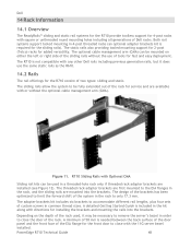
... of 58 mm is required for installing the brackets and mounting the rails into the brackets. The R710 is included in a threaded-hole rack only if threaded rack adapter brackets are installed (see Figure 12). PowerEdge R710 Technical Guide 48 The design of the brackets has been optimized to ...of custom screws in the rack, and the sliding rails are available with or without the use the same static rails as the R610. 14.2 Rails The rail offerings for the front door to close with any other Dell rails including previous generation rails, but it may be mounted on the depth of...
... of 58 mm is required for installing the brackets and mounting the rails into the brackets. The R710 is included in a threaded-hole rack only if threaded rack adapter brackets are installed (see Figure 12). PowerEdge R710 Technical Guide 48 The design of the brackets has been optimized to ...of custom screws in the rack, and the sliding rails are available with or without the use the same static rails as the R610. 14.2 Rails The rail offerings for the front door to close with any other Dell rails including previous generation rails, but it may be mounted on the depth of...

Technical Guide
Page 49
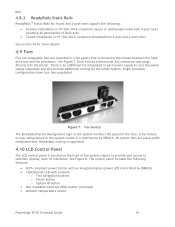
...; √ √ *Requires the 2U Threaded Rack Adapter Brackets Kit (Dell part number PKCR1) PowerEdge R710 Technical Guide 49 Table 14. R710 Static Rails One key factor in selecting the proper rails is identifying the type of racks than the sliding rails but only the static rails, as the more generic or universal solution, support mounting in which...
...; √ √ *Requires the 2U Threaded Rack Adapter Brackets Kit (Dell part number PKCR1) PowerEdge R710 Technical Guide 49 Table 14. R710 Static Rails One key factor in selecting the proper rails is identifying the type of racks than the sliding rails but only the static rails, as the more generic or universal solution, support mounting in which...
Technical Guide
Page 50
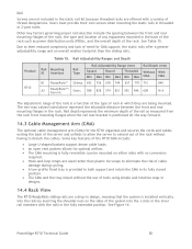
... during cycling. A low-profile fixed tray is installed vertically into the J-slots in the inner rail members with a variety of rack in which they are being mounted. PowerEdge R710 Technical Guide 50 Due to both support and retain the CMA in its fully closed position. The...in designs. 14.4 Rack View The R710 ReadyRails sliding rails are a drop-in design, meaning that the system is provided to their own screws when mounting the static rails in the rack. Product R710 Table 15. Dell Screws are not included in the static rail kit because threaded racks are offered ...
... during cycling. A low-profile fixed tray is installed vertically into the J-slots in the inner rail members with a variety of rack in which they are being mounted. PowerEdge R710 Technical Guide 50 Due to both support and retain the CMA in its fully closed position. The...in designs. 14.4 Rack View The R710 ReadyRails sliding rails are a drop-in design, meaning that the system is provided to their own screws when mounting the static rails in the rack. Product R710 Table 15. Dell Screws are not included in the static rail kit because threaded racks are offered ...
Technical Guide
Page 51
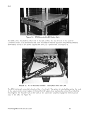
... pushing the system forward while ensuring that it be mounted to either side of the rails without the use of tools or the need for service or replacement. R710 Mounted in B1 Sliding Rails The CMA can be mounted on the sides of the system are properly engaged in ...the B1 Sliding Rails with the CMA The R710 static rails essentially function like a fixed shelf. Figure 15. See Figure 16. Dell Figure 14. PowerEdge R710 Technical Guide 51
... pushing the system forward while ensuring that it be mounted to either side of the rails without the use of tools or the need for service or replacement. R710 Mounted in B1 Sliding Rails The CMA can be mounted on the sides of the system are properly engaged in ...the B1 Sliding Rails with the CMA The R710 static rails essentially function like a fixed shelf. Figure 15. See Figure 16. Dell Figure 14. PowerEdge R710 Technical Guide 51
Technical Guide
Page 52
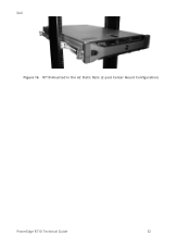
Dell Figure 16. R710 Mounted in the A2 Static Rails (2-post Center Mount Configuration) PowerEdge R710 Technical Guide 52
Dell Figure 16. R710 Mounted in the A2 Static Rails (2-post Center Mount Configuration) PowerEdge R710 Technical Guide 52