
Hardware Manual
Page 7
... Tape Backup Unit 110 Integrated Storage Controller Card 111 Removing the Integrated Storage Controller Card 112 Installing the Integrated Storage Controller Card 112 RAID Battery 116 Removing a RAID Battery 116 Installing a RAID Battery 117 Cable Routing 118 Removing the Cable Retention Bracket 118 Installing the Cable Retention Bracket 119 Expansion Cards and Expansion-Card Risers . . . . . 119...
... Tape Backup Unit 110 Integrated Storage Controller Card 111 Removing the Integrated Storage Controller Card 112 Installing the Integrated Storage Controller Card 112 RAID Battery 116 Removing a RAID Battery 116 Installing a RAID Battery 117 Cable Routing 118 Removing the Cable Retention Bracket 118 Installing the Cable Retention Bracket 119 Expansion Cards and Expansion-Card Risers . . . . . 119...
Hardware Manual
Page 24
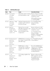
... Messages Code Text E1000 Failsafe voltage error. Reseat PCIe cards. If the problem persists, see "Getting Help." Table 1-1. Power cycle AC. Check battery. RAID battery is outside of the System Battery." Reseat the RAID battery connector. E1116 Memory disabled, temp above range. E1216 3.3V Regulator failure. allowable range. Remove AC power to thermal issues. See "Troubleshooting...
... Messages Code Text E1000 Failsafe voltage error. Reseat PCIe cards. If the problem persists, see "Getting Help." Table 1-1. Power cycle AC. Check battery. RAID battery is outside of the System Battery." Reseat the RAID battery connector. E1116 Memory disabled, temp above range. E1216 3.3V Regulator failure. allowable range. Remove AC power to thermal issues. See "Troubleshooting...
Hardware Manual
Page 36
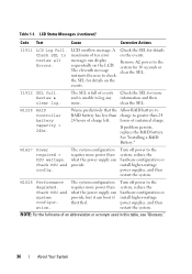
... config. Table 1-1. LCD overflow message. Review & clear log. Check the SEL for details on the LCD. If problem persists, replace the RAID battery. W1627 Power required > PSU wattage. Turn off power to log any more information and then clear the SEL. A maximum of charge left...restart the system. hours of an abbreviation or acronym used in this table, see "Glossary." 36 About Your System See "Installing a RAID Battery." The system configuration requires more power than 24 24 hours of ten error messages can display sequentially on the events. I1912 SEL full....
... config. Table 1-1. LCD overflow message. Review & clear log. Check the SEL for details on the LCD. If problem persists, replace the RAID battery. W1627 Power required > PSU wattage. Turn off power to log any more information and then clear the SEL. A maximum of charge left...restart the system. hours of an abbreviation or acronym used in this table, see "Glossary." 36 About Your System See "Installing a RAID Battery." The system configuration requires more power than 24 24 hours of ten error messages can display sequentially on the events. I1912 SEL full....
Hardware Manual
Page 76
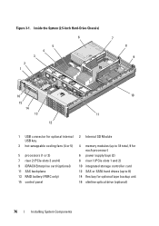
... connector for optional internal USB key 3 hot-swappable cooling fans (4 or 5) 5 processors (1 or 2) 7 riser 2 (PCIe slots 3 and 4) 9 iDRAC6 Enterprise card (optional) 11 SAS backplane 13 RAID battery (PERC only) 15 control panel 2 Internal SD Module 4 memory modules (up to 18 total, 9 for each processor) 6 power supply bays (2) 8 riser 1 (PCIe slots 1 and 2) 10...
... connector for optional internal USB key 3 hot-swappable cooling fans (4 or 5) 5 processors (1 or 2) 7 riser 2 (PCIe slots 3 and 4) 9 iDRAC6 Enterprise card (optional) 11 SAS backplane 13 RAID battery (PERC only) 15 control panel 2 Internal SD Module 4 memory modules (up to 18 total, 9 for each processor) 6 power supply bays (2) 8 riser 1 (PCIe slots 1 and 2) 10...
Hardware Manual
Page 112
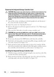
...as directed by your product documentation, or as authorized in controller memory and the data was not cleared at system shutdown. 5 If necessary, disconnect the RAID battery cable from the controller. 6 Bend both card-edge guides to release the controller, lift the side of the controller that data is lit. See ..., and disconnect the system from the storage controller card. Removing the Integrated Storage Controller Card CAUTION: Many repairs may only be done by Dell is adjacent to the blue guide, and then remove the controller out towards the rear of the chassis.
...as directed by your product documentation, or as authorized in controller memory and the data was not cleared at system shutdown. 5 If necessary, disconnect the RAID battery cable from the controller. 6 Bend both card-edge guides to release the controller, lift the side of the controller that data is lit. See ..., and disconnect the system from the storage controller card. Removing the Integrated Storage Controller Card CAUTION: Many repairs may only be done by Dell is adjacent to the blue guide, and then remove the controller out towards the rear of the chassis.
Hardware Manual
Page 113
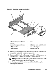
...to the controller's SAS_1 connector. Installing System Components 113 The cables are not operational if reversed. 5 For a battery-cached PERC controller, install the RAID battery. See "Installing a RAID Battery." Figure 3-20. Installing a Storage Controller Card 2 1 3 4 5 8 7 6 1 dedicated storage ...controller card connector 3 integrated storage controller card 5 SAS_1 connector 7 SAS_0 connector 2 riser 1 4 RAID battery connector (PERC only) 6 connector locking tabs 8 card edge guides (2) 3 Slide the storage controller's card edge connector into the...
...to the controller's SAS_1 connector. Installing System Components 113 The cables are not operational if reversed. 5 For a battery-cached PERC controller, install the RAID battery. See "Installing a RAID Battery." Figure 3-20. Installing a Storage Controller Card 2 1 3 4 5 8 7 6 1 dedicated storage ...controller card connector 3 integrated storage controller card 5 SAS_1 connector 7 SAS_0 connector 2 riser 1 4 RAID battery connector (PERC only) 6 connector locking tabs 8 card edge guides (2) 3 Slide the storage controller's card edge connector into the...
Hardware Manual
Page 114
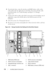
... your system and peripherals to the SAS B connector on the backplane. 8 Close the system. 6 If not already done, route the interface and RAID battery cables in Hard-Drive Chassis) 1 2 3 45 6 78 1 RAID battery (PERC only) 3 SAS A connector on backplane 5 integrated storage controller card 7 SAS_1 connector 2 SAS B connector on the system. See "Cable...connector on the backplane and, if applicable, connect the SAS B cable to their electrical outlets, and turn on backplane 4 cable retention bracket 6 SAS_0 connector 8 RAID battery connector (PERC only) 114 Installing System Components
... your system and peripherals to the SAS B connector on the backplane. 8 Close the system. 6 If not already done, route the interface and RAID battery cables in Hard-Drive Chassis) 1 2 3 45 6 78 1 RAID battery (PERC only) 3 SAS A connector on backplane 5 integrated storage controller card 7 SAS_1 connector 2 SAS B connector on the system. See "Cable...connector on the backplane and, if applicable, connect the SAS B cable to their electrical outlets, and turn on backplane 4 cable retention bracket 6 SAS_0 connector 8 RAID battery connector (PERC only) 114 Installing System Components
Hardware Manual
Page 115
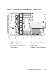
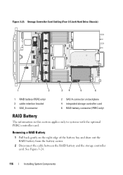
Storage Controller Card Cabling (Six 3.5-in Hard-Drive Chassis) 1 2 3 45 6 78 1 RAID battery (PERC only) 3 SAS A connector on backplane 5 integrated storage controller card 7 SAS_1 connector 2 SAS B connector on backplane 4 cable retention bracket 6 SAS_0 connector 8 RAID battery connector (PERC only) Installing System Components 115 Figure 3-22.
Storage Controller Card Cabling (Six 3.5-in Hard-Drive Chassis) 1 2 3 45 6 78 1 RAID battery (PERC only) 3 SAS A connector on backplane 5 integrated storage controller card 7 SAS_1 connector 2 SAS B connector on backplane 4 cable retention bracket 6 SAS_0 connector 8 RAID battery connector (PERC only) Installing System Components 115 Figure 3-22.
Hardware Manual
Page 116
... the optional PERC controller card. Storage Controller Card Cabling (Four 3.5-inch Hard Drive Chassis) 1 2 34 5 6 1 RAID battery (PERC only) 3 cable retention bracket 5 SAS_0 connector 2 SAS A connector on the right edge of the battery bay and draw out the RAID battery from the battery carrier. 2 Disconnect the cable between the RAID battery and the storage controller card. Figure 3-23.
... the optional PERC controller card. Storage Controller Card Cabling (Four 3.5-inch Hard Drive Chassis) 1 2 34 5 6 1 RAID battery (PERC only) 3 cable retention bracket 5 SAS_0 connector 2 SAS A connector on the right edge of the battery bay and draw out the RAID battery from the battery carrier. 2 Disconnect the cable between the RAID battery and the storage controller card. Figure 3-23.
Hardware Manual
Page 117
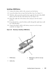
See Figure 3-20. Removing or Installing a RAID Battery 2 1 1 RAID battery 3 battery bay 3 2 RAID battery cable from storage controller Installing System Components 117 Installing a RAID Battery 1 Connect the battery cable to the battery connector on top of the hard drive bays. See Figure 3-24. 4 Rotate the right side of the battery down and press into the left side of the battery bay. See Figure 3-1. 3 With...
See Figure 3-20. Removing or Installing a RAID Battery 2 1 1 RAID battery 3 battery bay 3 2 RAID battery cable from storage controller Installing System Components 117 Installing a RAID Battery 1 Connect the battery cable to the battery connector on top of the hard drive bays. See Figure 3-24. 4 Rotate the right side of the battery down and press into the left side of the battery bay. See Figure 3-1. 3 With...
Hardware Manual
Page 151
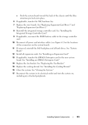
... the system board). 11 If removed, reinstall the SAS backplane and all expansion cards. See "Installing the Integrated Storage Controller Card." 9 If applicable, reconnect the RAID battery cable to the new system board. Installing System Components 151 See "Replacing the Fan Bracket." 15 Replace the cooling shroud. See "Installing an Expansion Card...
... the system board). 11 If removed, reinstall the SAS backplane and all expansion cards. See "Installing the Integrated Storage Controller Card." 9 If applicable, reconnect the RAID battery cable to the new system board. Installing System Components 151 See "Replacing the Fan Bracket." 15 Replace the cooling shroud. See "Installing an Expansion Card...
Hardware Manual
Page 168
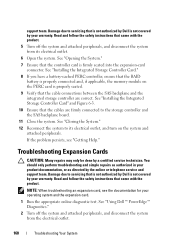
... system and attached peripherals. See "Using Dell™ PowerEdge™ Diagnostics." 2 Turn off the system and attached peripherals, and disconnect the system from the electrical outlet. 168 Troubleshooting Your System See "Installing the Integrated Storage Controller Card." 8 If you have a battery-cached PERC controller, ensure that the RAID battery is firmly seated into the expansion...
... system and attached peripherals. See "Using Dell™ PowerEdge™ Diagnostics." 2 Turn off the system and attached peripherals, and disconnect the system from the electrical outlet. 168 Troubleshooting Your System See "Installing the Integrated Storage Controller Card." 8 If you have a battery-cached PERC controller, ensure that the RAID battery is firmly seated into the expansion...
Hardware Manual
Page 201
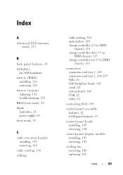
Index A Advanced ECC memory mode, 131 B back panel features, 19 backplane See SAS backplane. battery (RAID) installing, 116 removing, 116 battery (system) replacing, 141 troubleshooting, 158 BIOS boot mode, 55 blank hard drive, 81 power supply, 88 boot mode, 55 C cable retention bracket ... 1, 185 expansion-card riser 2, 186-187 NIC, 20 SAS backplane board, 182 serial, 20 system board, 180 USB, 12 video, 12 contacting Dell, 189 control panel assembly features, 12 LCD panel features, 15 control panel board installing, 145 removing, 144 control panel display module installing, 143 removing,...
Index A Advanced ECC memory mode, 131 B back panel features, 19 backplane See SAS backplane. battery (RAID) installing, 116 removing, 116 battery (system) replacing, 141 troubleshooting, 158 BIOS boot mode, 55 blank hard drive, 81 power supply, 88 boot mode, 55 C cable retention bracket ... 1, 185 expansion-card riser 2, 186-187 NIC, 20 SAS backplane board, 182 serial, 20 system board, 180 USB, 12 video, 12 contacting Dell, 189 control panel assembly features, 12 LCD panel features, 15 control panel board installing, 145 removing, 144 control panel display module installing, 143 removing,...
Hardware Manual
Page 203
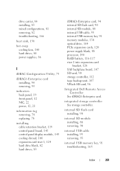
...cable, 93 internal USB memory key, 91 memory modules, 134 optical drive, 104 PCIe expansion cards, 120 power supply blank, 88 processor, 140 RAID battery, 116-117 riser 2 into expansion-card bracket, 128 SAS backplane board, 147 SD card, 90 storage controller, 112 tape backup unit, 107 ...VFlash SD card, 96 Integrated Dell Remote Access Controller See iDRAC6 Enterprise card. integrated storage controller See storage controller. internal SD flash card installing, 90 internal SD module installing, ...
...cable, 93 internal USB memory key, 91 memory modules, 134 optical drive, 104 PCIe expansion cards, 120 power supply blank, 88 processor, 140 RAID battery, 116-117 riser 2 into expansion-card bracket, 128 SAS backplane board, 147 SD card, 90 storage controller, 112 tape backup unit, 107 ...VFlash SD card, 96 Integrated Dell Remote Access Controller See iDRAC6 Enterprise card. integrated storage controller See storage controller. internal SD flash card installing, 90 internal SD module installing, ...
Hardware Manual
Page 205
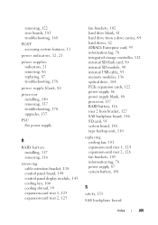
R RAID battery installing, 117 removing, 116 removing cable retention bracket, 118 control panel board...memory modules, 136 optical drive, 104 PCIe expansion cards, 122 power supply, 86 power supply blank, 88 processor, 137 RAID battery, 116 riser 2 from bracket, 127 SAS backplane board, 146 SD card, 91 system board, 148 tape backup unit... expansion-card riser 1, 124 expansion-card riser 2, 126 fan brackets, 103 information tag, 78 power supply, 87 system battery, 141 S safety, 153 SAS backplane board Index 205 removing, 122 riser boards, 185 troubleshooting, 168 POST accessing system features...
R RAID battery installing, 117 removing, 116 removing cable retention bracket, 118 control panel board...memory modules, 136 optical drive, 104 PCIe expansion cards, 122 power supply, 86 power supply blank, 88 processor, 137 RAID battery, 116 riser 2 from bracket, 127 SAS backplane board, 146 SD card, 91 system board, 148 tape backup unit... expansion-card riser 1, 124 expansion-card riser 2, 126 fan brackets, 103 information tag, 78 power supply, 87 system battery, 141 S safety, 153 SAS backplane board Index 205 removing, 122 riser boards, 185 troubleshooting, 168 POST accessing system features...
Technical Guide
Page 12
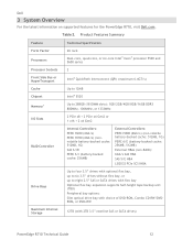
... Controllers: PERC H200 (6Gb/s) PERC H700 (6Gb/s) (nonvolatile battery-backed cache: 512MB, 1G) SAS 6/iR PERC 6/i (battery-backed cache: 256MB) External Controllers: PERC H800 (6Gb/s) (non-volatile battery-backed cache: 512MB, 1G) PERC 6/E (battery-backed cache: 256MB, 512MB) External HBAs (non-RAID): 6Gb/s SAS HBA SAS 5/E HBA LSI2032 PCIe SCSI HBA...of DVD-ROM, Combo CD-RW/DVDROM, or DVD+RW Maximum Internal Storage 12TB (with 2TB 3.5‖ nearline SAS or SATA drives) PowerEdge R710 Technical Guide 12 Table 2. Dell 3 System Overview For the latest information on supported features for the...
... Controllers: PERC H200 (6Gb/s) PERC H700 (6Gb/s) (nonvolatile battery-backed cache: 512MB, 1G) SAS 6/iR PERC 6/i (battery-backed cache: 256MB) External Controllers: PERC H800 (6Gb/s) (non-volatile battery-backed cache: 512MB, 1G) PERC 6/E (battery-backed cache: 256MB, 512MB) External HBAs (non-RAID): 6Gb/s SAS HBA SAS 5/E HBA LSI2032 PCIe SCSI HBA...of DVD-ROM, Combo CD-RW/DVDROM, or DVD+RW Maximum Internal Storage 12TB (with 2TB 3.5‖ nearline SAS or SATA drives) PowerEdge R710 Technical Guide 12 Table 2. Dell 3 System Overview For the latest information on supported features for the...

Technical Guide
Page 44
... A battery is also available for connection to be used in the PowerEdge R610 and PowerEdge T610. 12.4.2 PERC 6/i If you want an internal RAID solution,... select the PERC 6/i or PERC H700. It is designed in a form factor that allows the same card to SAS or SATA hard disk drives. It incorporates two four-channel 6 Gb.... PowerEdge R710 Technical Guide 44 The PERC 6/i uses the LSI 1078 ROC (RAID on Riser1. Dell Config Type Configs Description Integrated SAS/SATA RAID 15 MSSR1/R10-X 1/RAID 10...
... A battery is also available for connection to be used in the PowerEdge R610 and PowerEdge T610. 12.4.2 PERC 6/i If you want an internal RAID solution,... select the PERC 6/i or PERC H700. It is designed in a form factor that allows the same card to SAS or SATA hard disk drives. It incorporates two four-channel 6 Gb.... PowerEdge R710 Technical Guide 44 The PERC 6/i uses the LSI 1078 ROC (RAID on Riser1. Dell Config Type Configs Description Integrated SAS/SATA RAID 15 MSSR1/R10-X 1/RAID 10...
Technical Guide
Page 45
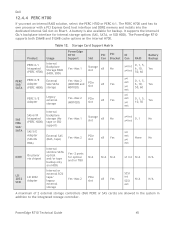
... internal 6 Gb/s backplane interface for optical and/or TBU N/A (no HDD) Internal or external SCSI tape/ legacy Yes-Max 2 PCIe slot external storage N/A N/A x8 Yes x1 int N/A N/A SCSI int N/A N/A SCSI ext A maximum of 2 external storage controllers (Dell PERC or ...Product PERC 6/i Integrated (PERC H700) Usage Internal Backplane Storage RAID (HDD, SDD) PERC 6/E Adapter (PERC H800) External SAS/SATA storage PERC 5/E Adapter Legacy external storage PowerEdge R710 Support Slot PCI PCI IO Con Bracket Con RAID Battery Backup Yes-Max 1 Storage slot x8 No x4 int 0,...
... internal 6 Gb/s backplane interface for optical and/or TBU N/A (no HDD) Internal or external SCSI tape/ legacy Yes-Max 2 PCIe slot external storage N/A N/A x8 Yes x1 int N/A N/A SCSI int N/A N/A SCSI ext A maximum of 2 external storage controllers (Dell PERC or ...Product PERC 6/i Integrated (PERC H700) Usage Internal Backplane Storage RAID (HDD, SDD) PERC 6/E Adapter (PERC H800) External SAS/SATA storage PERC 5/E Adapter Legacy external storage PowerEdge R710 Support Slot PCI PCI IO Con Bracket Con RAID Battery Backup Yes-Max 1 Storage slot x8 No x4 int 0,...


