
Owners Manual
Page 19
...memory card for the optional iDRAC6 Enterprise card. Connects USB devices to the system. Back-Panel Features and Indicators Figure 1-4 shows the controls, indicators, and connectors located on indicator for the back of the system About Your System 19 PCI Express (generation 2) x8-wide expansion slot...iDRAC6 Enterprise card. The ports are USB 2.0-complaint. Connects a serial device to the system. Figure 1-4. PCIe Gen2 x8-wide expansion slot (full-height, half-length) Embedded 10/100/1000 NIC connectors. Connector for attaching a system indicator extension cable that is used ...
...memory card for the optional iDRAC6 Enterprise card. Connects USB devices to the system. Back-Panel Features and Indicators Figure 1-4 shows the controls, indicators, and connectors located on indicator for the back of the system About Your System 19 PCI Express (generation 2) x8-wide expansion slot...iDRAC6 Enterprise card. The ports are USB 2.0-complaint. Connects a serial device to the system. Figure 1-4. PCIe Gen2 x8-wide expansion slot (full-height, half-length) Embedded 10/100/1000 NIC connectors. Connector for attaching a system indicator extension cable that is used ...

Owners Manual
Page 35
... Remove AC power to log any more. The SEL is full of ten error messages can display sequentially on the events. see "Troubleshooting System Memory." System cover has been removed. A maximum of events and is rebooted. I1912 SEL full. E2111 SBE log disabled on DIMM ##. About Your... System 35 Table 1-1. LCD Status Messages (continued) Code Text Cause Corrective Actions E2110 Multibit Error on DIMM ##. The DIMM in slot "##" has had too many errors. Reseat DIMM. not log anymore SBEs until If the problem persists, the system is unable to the...
... Remove AC power to log any more. The SEL is full of ten error messages can display sequentially on the events. see "Troubleshooting System Memory." System cover has been removed. A maximum of events and is rebooted. I1912 SEL full. E2111 SBE log disabled on DIMM ##. About Your... System 35 Table 1-1. LCD Status Messages (continued) Code Text Cause Corrective Actions E2110 Multibit Error on DIMM ##. The DIMM in slot "##" has had too many errors. Reseat DIMM. not log anymore SBEs until If the problem persists, the system is unable to the...
Owners Manual
Page 40
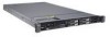
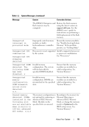
... CPU x installed with no memory. Install memory modules for possible causes. See "System Memory." 40 About Your System If the problem persists, see "Getting Help." After restoring the jumper, update the desired settings in the indicated processor's memory slots. See "Using the System ...Setup Program and UEFI Boot Manager." System Messages (continued) Message Causes Corrective Actions BIOS Update Remote BIOS update Attempt Failed! Memory modules are required but not installed in the...
... CPU x installed with no memory. Install memory modules for possible causes. See "System Memory." 40 About Your System If the problem persists, see "Getting Help." After restoring the jumper, update the desired settings in the indicated processor's memory slots. See "Using the System ...Setup Program and UEFI Boot Manager." System Messages (continued) Message Causes Corrective Actions BIOS Update Remote BIOS update Attempt Failed! Memory modules are required but not installed in the...
Owners Manual
Page 43
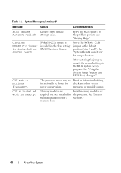
... Card." failed keyboard connector. The following DIMM has been disabled: x Invalid memory configuration. Remove the PCIe expansion card and install the integrated storage controller in the slot! out of manufacturing mode. About Your System 43 Keyboard fuse has Overcurrent detected... at the See "Getting Help." Manufacturing mode detected System is defective. Ensure that the memory modules are installed in manufacturing ...
... Card." failed keyboard connector. The following DIMM has been disabled: x Invalid memory configuration. Remove the PCIe expansion card and install the integrated storage controller in the slot! out of manufacturing mode. About Your System 43 Keyboard fuse has Overcurrent detected... at the See "Getting Help." Manufacturing mode detected System is defective. Ensure that the memory modules are installed in manufacturing ...
Owners Manual
Page 46
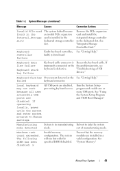
...in the clear position (pins 1 and 3) and reboot the system. If the problem persists, see "Getting Help." See "System Memory." 46 About Your System "Troubleshooting Expansion Actual Link Width Cards." PCIe Training Faulty or improperly installed Reseat the PCIe card in the ...Quad rank DIMM detected after single rank or dual rank DIMM in the specified specified slot number. faulty or improperly installed expansion card(s). Table 1-2. If the problem is x, slot. System Messages (continued) Message Causes Corrective Actions PCI BIOS failed to the expansion card...
...in the clear position (pins 1 and 3) and reboot the system. If the problem persists, see "Getting Help." See "System Memory." 46 About Your System "Troubleshooting Expansion Actual Link Width Cards." PCIe Training Faulty or improperly installed Reseat the PCIe card in the ...Quad rank DIMM detected after single rank or dual rank DIMM in the specified specified slot number. faulty or improperly installed expansion card(s). Table 1-2. If the problem is x, slot. System Messages (continued) Message Causes Corrective Actions PCI BIOS failed to the expansion card...
Owners Manual
Page 51
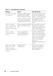
...: x,x,... mode to Optimized in the when in a valid configuration. Unsupported DIMM detected. support.dell.com. Unused memory The memory configuration is not supported Install a supported processor by the system. Modules in the Mode, or change the memory are not available specified slots are installed in mirror or BIOS setup screen. System Messages (continued) Message Causes...
...: x,x,... mode to Optimized in the when in a valid configuration. Unsupported DIMM detected. support.dell.com. Unused memory The memory configuration is not supported Install a supported processor by the system. Modules in the Mode, or change the memory are not available specified slots are installed in mirror or BIOS setup screen. System Messages (continued) Message Causes...

Owners Manual
Page 98
...and restart the system. Internal USB Memory Key The USB memory key can be done by a certified service technician. Damage due to servicing that is not authorized by Dell is not covered by your warranty. See "Opening the System." 3 Locate the SD card slot on the internal SD module and... press inward on the USB memory key, see the user documentation that came with a boot image ...
...and restart the system. Internal USB Memory Key The USB memory key can be done by a certified service technician. Damage due to servicing that is not authorized by Dell is not covered by your warranty. See "Opening the System." 3 Locate the SD card slot on the internal SD module and... press inward on the USB memory key, see the user documentation that came with a boot image ...
Owners Manual
Page 111
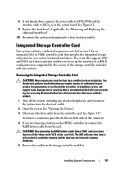
... 4 If you to servicing that came with your system's internal hard drives. Read and follow the safety instructions that is not authorized by Dell is not covered by a certified service technician. To remove a connector, press the latches on riser 1 for an integrated SAS or PERC ...Figure 3-17. You should only perform troubleshooting and simple repairs as authorized in controller memory and the data was not cleared at system shutdown. 5 Remove the card from the storage controller card slot: Installing System Components 111 The controller supports SAS and SATA hard drives and also ...
... 4 If you to servicing that came with your system's internal hard drives. Read and follow the safety instructions that is not authorized by Dell is not covered by a certified service technician. To remove a connector, press the latches on riser 1 for an integrated SAS or PERC ...Figure 3-17. You should only perform troubleshooting and simple repairs as authorized in controller memory and the data was not cleared at system shutdown. 5 Remove the card from the storage controller card slot: Installing System Components 111 The controller supports SAS and SATA hard drives and also ...

Owners Manual
Page 117
... selected. Mirroring must be installed in the sockets with the white release levers. • If memory modules with identical memory modules. and x8-based memory modules. In a mirrored configuration, the total available system memory is not installed in corresponding slots. Optimizer (Independent Channel) Mode In this configuration, the two channels closest to the processor are...
... selected. Mirroring must be installed in the sockets with the white release levers. • If memory modules with identical memory modules. and x8-based memory modules. In a mirrored configuration, the total available system memory is not installed in corresponding slots. Optimizer (Independent Channel) Mode In this configuration, the two channels closest to the processor are...

Owners Manual
Page 138
... the label placard that all retention hooks on the bottom of the chassis are inserted into the retention slots on the system board. See "Removing a Processor" and "Installing a Processor." 4 Remove the memory modules and transfer them to the same locations on the system board): • SATA interface cable, if...system board tray, lower the right side of the system board into the chassis. See "NIC Hardware Key." 7 Connect the cables in the memory module socket. 2 Remove the labels from the placard and affix them to the system information panel on the front of the connectors on the...
... the label placard that all retention hooks on the bottom of the chassis are inserted into the retention slots on the system board. See "Removing a Processor" and "Installing a Processor." 4 Remove the memory modules and transfer them to the same locations on the system board): • SATA interface cable, if...system board tray, lower the right side of the system board into the chassis. See "NIC Hardware Key." 7 Connect the cables in the memory module socket. 2 Remove the labels from the placard and affix them to the system information panel on the front of the connectors on the...

Owners Manual
Page 166
... iDRAC6 Enterprise card connector 5 SATA_A optical drive interface connector 6 B1 B4 B2 B5 B3 B6 memory module slot B1 (white release lever) memory module slot B4 memory module slot B2 (white release lever) memory module slot B5 memory module slot B3 (white release lever) memory module slot B6 7 CPU2 processor socket 2 8 CPU1 processor socket 1 9 BATTERY connector for the 3.0-V coin battery 10 FAN_MODn...
... iDRAC6 Enterprise card connector 5 SATA_A optical drive interface connector 6 B1 B4 B2 B5 B3 B6 memory module slot B1 (white release lever) memory module slot B4 memory module slot B2 (white release lever) memory module slot B5 memory module slot B3 (white release lever) memory module slot B6 7 CPU2 processor socket 2 8 CPU1 processor socket 1 9 BATTERY connector for the 3.0-V coin battery 10 FAN_MODn...

Owners Manual
Page 176
... mice and keyboards. VAC - A video adapter may be integrated into an expansion slot. To display a program at each end of an electrical failure. uplink port - See memory key. video adapter - TCP/IP - When such devices are connected in a ...series, you must support the resolution. 176 Glossary TCP/IP offload engine. UEFI - A port on the devices or by the number of colors that automatically supplies power to your monitor must install the appropriate video drivers and your system's RAM...
... mice and keyboards. VAC - A video adapter may be integrated into an expansion slot. To display a program at each end of an electrical failure. uplink port - See memory key. video adapter - TCP/IP - When such devices are connected in a ...series, you must support the resolution. 176 Glossary TCP/IP offload engine. UEFI - A port on the devices or by the number of colors that automatically supplies power to your monitor must install the appropriate video drivers and your system's RAM...

Owners Manual
Page 180
...161 using Dell PowerEdge Diagnostics, 159 when to use, 160 DIMMs See memory modules (DIMMs). drive blank installing, 83 removing, 82 drive carrier hard drive, 85 E error messages, 58 expansion cards installing, 90 removing, 92 SAS controller, 111 troubleshooting, 155 expansion slots, 89 ...F front-panel features, 12 G guidelines expansion card installation, 89 memory installation, 116 180 Index H hard drive drive carrier, 85 installing, 84 removing, 83 troubleshooting...
...161 using Dell PowerEdge Diagnostics, 159 when to use, 160 DIMMs See memory modules (DIMMs). drive blank installing, 83 removing, 82 drive carrier hard drive, 85 E error messages, 58 expansion cards installing, 90 removing, 92 SAS controller, 111 troubleshooting, 155 expansion slots, 89 ...F front-panel features, 12 G guidelines expansion card installation, 89 memory installation, 116 180 Index H hard drive drive carrier, 85 installing, 84 removing, 83 troubleshooting...
Owners Manual
Page 183
...system, 68, 73 service-only procedure system board, 135 setup password, 74 slots See expansion slots. startup accessing system features, 11 support contacting Dell, 167 system closing, 81 opening, 80 system board connectors, 164 installing, ...138 jumpers, 163 removing, 135 system cooling troubleshooting, 147 system features accessing, 11 system messages, 37 system password, 72 system setup program boot settings, 63 embedded server management options, 66 integrated devices options, 64 keystroke to enter, 58 memory...
...system, 68, 73 service-only procedure system board, 135 setup password, 74 slots See expansion slots. startup accessing system features, 11 support contacting Dell, 167 system closing, 81 opening, 80 system board connectors, 164 installing, ...138 jumpers, 163 removing, 135 system cooling troubleshooting, 147 system features accessing, 11 system messages, 37 system password, 72 system setup program boot settings, 63 embedded server management options, 66 integrated devices options, 64 keystroke to enter, 58 memory...


