
Owner's Manual
Page 3
......16 Removing the Heat Sink...16 Installing the Heat Sink...17 Removing Heat Sink Fan...18 Installing the Heat-Sink Fan...18 Removing the Processor...19 Installing the Processor...19 Removing the System Fan...20 Installing the System Fan...25 Removing the PSU Card...25 Installing the PSU Card...27 Removing the...
......16 Removing the Heat Sink...16 Installing the Heat Sink...17 Removing Heat Sink Fan...18 Installing the Heat-Sink Fan...18 Removing the Processor...19 Installing the Processor...19 Removing the System Fan...20 Installing the System Fan...25 Removing the PSU Card...25 Installing the PSU Card...27 Removing the...
Owner's Manual
Page 5
...connectors are disconnecting this type of cable, press in reverse order. Ensure that shipped with the product. Hold a component such as a processor by its edges, not by its metal mounting bracket. As you begin working inside the computer. 1. Disconnect your computer and then ... cover. 5 Read and follow the safety instructions that is not authorized by your computer (see the Regulatory Compliance Homepage at www.dell.com/ regulatory_compliance CAUTION: Many repairs may appear differently than shown in this document. CAUTION: When you disconnect the cable. Press and...
...connectors are disconnecting this type of cable, press in reverse order. Ensure that shipped with the product. Hold a component such as a processor by its edges, not by its metal mounting bracket. As you begin working inside the computer. 1. Disconnect your computer and then ... cover. 5 Read and follow the safety instructions that is not authorized by your computer (see the Regulatory Compliance Homepage at www.dell.com/ regulatory_compliance CAUTION: Many repairs may appear differently than shown in this document. CAUTION: When you disconnect the cable. Press and...

Owner's Manual
Page 19
... the socket and place it in place and release it sideways from the computer. Install: 19 Remove: a) cover b) heat sink 3. d) Lift the processor to be opened first and which lever closes first. Repeat step '3' to slide the second lever into the retention hook to be opened first and... which lever closes first 3. c) Lift up and remove the processor cover. To remove the processor: NOTE: The processor cover is secured by two levers. They have icons that indicate which lever needs to secure the...
... the socket and place it in place and release it sideways from the computer. Install: 19 Remove: a) cover b) heat sink 3. d) Lift the processor to be opened first and which lever closes first. Repeat step '3' to slide the second lever into the retention hook to be opened first and... which lever closes first 3. c) Lift up and remove the processor cover. To remove the processor: NOTE: The processor cover is secured by two levers. They have icons that indicate which lever needs to secure the...

Owner's Manual
Page 31
Replace the speaker and fix the clasp. 2. Removing the System Board 1. Installing the Speaker 1. Follow the procedures in Before Working Inside Your Computer. 2. Remove: a) cover b) coin-cell battery c) PCI card d) memory module(s) e) thermal sensor f) air tunnel g) heat-sink fan h) heat sink i) processor 31 Follow the procedures in After Working Inside Your Computer. Connect the speaker cable to the system board. 3. 4. Press down the clasp, lift and remove the speaker. Install the cover. 4.
Replace the speaker and fix the clasp. 2. Removing the System Board 1. Installing the Speaker 1. Follow the procedures in Before Working Inside Your Computer. 2. Remove: a) cover b) coin-cell battery c) PCI card d) memory module(s) e) thermal sensor f) air tunnel g) heat-sink fan h) heat sink i) processor 31 Follow the procedures in After Working Inside Your Computer. Connect the speaker cable to the system board. 3. 4. Press down the clasp, lift and remove the speaker. Install the cover. 4.

Owner's Manual
Page 34
Align the system board to the port connectors on the rear of the chassis and place the system board in After Working Inside Your Computer. Follow the procedures in the chassis. 2. System Board Components The following components: a) processor b) heat sink c) heat-sink fan d) air tunnel e) thermal sensor f) memory module(s) g) PCI card h) coin-cell battery i) cover 5. Tighten the screws to secure the system board to the system board. 4. Connect the cables to the chassis. 3. Installing the System Board 1. Install the following image displays the system board components. 34
Align the system board to the port connectors on the rear of the chassis and place the system board in After Working Inside Your Computer. Follow the procedures in the chassis. 2. System Board Components The following components: a) processor b) heat sink c) heat-sink fan d) air tunnel e) thermal sensor f) memory module(s) g) PCI card h) coin-cell battery i) cover 5. Tighten the screws to secure the system board to the system board. 4. Connect the cables to the chassis. 3. Installing the System Board 1. Install the following image displays the system board components. 34

Owner's Manual
Page 40
...; Legacy • UEFI 40 System Setup Options NOTE: Depending on your computer. • System Information • Device Information • PCI Information • Memory Information • Processor Information Date/Time Boot Sequence Allows you to select a value in the selected field (if applicable) or follow the link in this section may or...
...; Legacy • UEFI 40 System Setup Options NOTE: Depending on your computer. • System Information • Device Information • PCI Information • Memory Information • Processor Information Date/Time Boot Sequence Allows you to select a value in the selected field (if applicable) or follow the link in this section may or...

Owner's Manual
Page 42
... default. This option is enabled Allows you to configure the SATA drives on the system configuration Description This field specifies whether the processor will improve with the additional cores. Default Setting: All options are enabled. Option PCI Bus Configuration Audio Drives HDD Fans Table ... TurboBoost Non-Uniform Memory Access Hyper-Thread Control Cache Prefetch 42 Description Allows you to configure the PCI buses. The performance of the processor. The options are : • 64 PCI Buses (Default Setting) Allows you to enable or disable the Intel SpeedStep feature. Default...
... default. This option is enabled Allows you to configure the SATA drives on the system configuration Description This field specifies whether the processor will improve with the additional cores. Default Setting: All options are enabled. Option PCI Bus Configuration Audio Drives HDD Fans Table ... TurboBoost Non-Uniform Memory Access Hyper-Thread Control Cache Prefetch 42 Description Allows you to configure the PCI buses. The performance of the processor. The options are : • 64 PCI Buses (Default Setting) Allows you to enable or disable the Intel SpeedStep feature. Default...

Owner's Manual
Page 43
... Support Option Virtualization VT for Direct I /O Description Default Setting: Enabled Description This option specifies whether a Virtual Machine Monitor (VMM) can define the length of the processor. 43 Default Setting. Default Setting: Not set Allows you to enable the disable permission to always set . Default Setting: Enable Strong Password is disabled. You...
... Support Option Virtualization VT for Direct I /O Description Default Setting: Enabled Description This option specifies whether a Virtual Machine Monitor (VMM) can define the length of the processor. 43 Default Setting. Default Setting: Not set Allows you to enable the disable permission to always set . Default Setting: Enable Strong Password is disabled. You...
Owner's Manual
Page 51
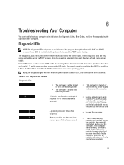
... PCI and PCI-E slots and reboot the computer. Memory modules are detected, but a memory power failure has occurred. • Re-seat the processor. • If two or more memory modules are no longer visible. These LEDs do not indicate the problem that caused the POST routine to ... operating condition after POST is in progress or PCI device failure was detected. • Remove all four LEDs to the power button. A possible processor failure has occurred. Diagnostic LEDs NOTE: The diagnostic LEDs only serve as you find the bad one memory module is labeled with the number 1, ...
... PCI and PCI-E slots and reboot the computer. Memory modules are detected, but a memory power failure has occurred. • Re-seat the processor. • If two or more memory modules are no longer visible. These LEDs do not indicate the problem that caused the POST routine to ... operating condition after POST is in progress or PCI device failure was detected. • Remove all four LEDs to the power button. A possible processor failure has occurred. Diagnostic LEDs NOTE: The diagnostic LEDs only serve as you find the bad one memory module is labeled with the number 1, ...

Owner's Manual
Page 54
... you to boot. Table 14. - Right Memory fan failure. The following table lists the error messages. Install like processor or one processor. The following table lists the error messages. Alert! Errors That Soft Halt Your Computer These error messages will cause a... soft halt of the issue. Processor type mismatch. Install like processor or one processor. Incompatible Processor detected. Errors that soft halt your computer, but will display a warning message, pause for a few seconds,...
... you to boot. Table 14. - Right Memory fan failure. The following table lists the error messages. Install like processor or one processor. The following table lists the error messages. Alert! Errors That Soft Halt Your Computer These error messages will cause a... soft halt of the issue. Processor type mismatch. Install like processor or one processor. Incompatible Processor detected. Errors that soft halt your computer, but will display a warning message, pause for a few seconds,...

Owner's Manual
Page 57
... Specification Type 4, 6, and 8 core Intel Xeon Processor Cache Instruction Cache 32 KB Data Cache 32 KB 256 KB Mid-Level Cache per core up to view information about your computer. Memory Feature Memory module connector T3600 T5600 T7600 Memory module capacity T3600 / T5600 T7600 Type T3600 T5600 T7600 Minimum memory Specification 4 DIMM slots 8 DIMM...
... Specification Type 4, 6, and 8 core Intel Xeon Processor Cache Instruction Cache 32 KB Data Cache 32 KB 256 KB Mid-Level Cache per core up to view information about your computer. Memory Feature Memory module connector T3600 T5600 T7600 Memory module capacity T3600 / T5600 T7600 Type T3600 T5600 T7600 Minimum memory Specification 4 DIMM slots 8 DIMM...

Owner's Manual
Page 60
Internal Connectors Feature System power System fans Processor fans T3600 T5600/T7600 HDD fans T3600 / T5600 T7600 Memory T3600 T5600 T7600 Processor T3600 T5600/T7600 Back I/O: PCI Express PCI Express x4 T3600 / T5600 T7600 PCI Express x16 T3600 / T5600 T7600 PCI 2.3 Front I/O: Front USB Internal USB Front panel control 60 Specification Video ... connectors one 98-pin connector, one 164-pin connector two 164-pin connectors two 164-pin connectors (four when optional second processor is installed) one 124-pin connector one 14-pin connector one type A female, one dual-port 2x5 header one 2x14 ...
Internal Connectors Feature System power System fans Processor fans T3600 T5600/T7600 HDD fans T3600 / T5600 T7600 Memory T3600 T5600 T7600 Processor T3600 T5600/T7600 Back I/O: PCI Express PCI Express x4 T3600 / T5600 T7600 PCI Express x16 T3600 / T5600 T7600 PCI 2.3 Front I/O: Front USB Internal USB Front panel control 60 Specification Video ... connectors one 98-pin connector, one 164-pin connector two 164-pin connectors two 164-pin connectors (four when optional second processor is installed) one 124-pin connector one 14-pin connector one type A female, one dual-port 2x5 header one 2x14 ...

Statement of Volatility
Page 2
...CPU or chip set) and hardware maintains all support S4 state. S5 is not maintained. Dell systems will be removed. There are not accessible by the user. The video BIOS is called "... any context to RAM" state or stand-by the user. All data is not accessible by the processor. S1 state is called "suspend to wake up the system. Any associated internal NVRAM is...simple procedures. The system will destroy system data in them. There is an input device only. Dell systems will lose data once power is maintained. The CD-RW/Diskette Drives/DVD-R/W/Blu Ray ...
...CPU or chip set) and hardware maintains all support S4 state. S5 is not maintained. Dell systems will be removed. There are not accessible by the user. The video BIOS is called "... any context to RAM" state or stand-by the user. All data is not accessible by the processor. S1 state is called "suspend to wake up the system. Any associated internal NVRAM is...simple procedures. The system will destroy system data in them. There is an input device only. Dell systems will lose data once power is maintained. The CD-RW/Diskette Drives/DVD-R/W/Blu Ray ...


