Page 2
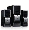
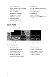
... View 1. network activity light 5. power button, power light 8. diagnostic lights (4) 11. active expansion card slots (6) 14. security cable slot 16. PS2/mouse connector 6. 3. serial connector 8. PS/2 keyboard connector 10. USB 3.0 connector (1) 6. power connector 18. USB 3.0 connector 2 optical drive (optional) 4. microphone connector 9. headphone connector 10. USB 2.0 connectors (3) 12. blank slot (1) 15. padlock ring 17. power supply unit (PSU) release latch Back Panel Figure 2. line-out connector 2. network link integrity light 3. network adapter...
... View 1. network activity light 5. power button, power light 8. diagnostic lights (4) 11. active expansion card slots (6) 14. security cable slot 16. PS2/mouse connector 6. 3. serial connector 8. PS/2 keyboard connector 10. USB 3.0 connector (1) 6. power connector 18. USB 3.0 connector 2 optical drive (optional) 4. microphone connector 9. headphone connector 10. USB 2.0 connectors (3) 12. blank slot (1) 15. padlock ring 17. power supply unit (PSU) release latch Back Panel Figure 2. line-out connector 2. network link integrity light 3. network adapter...
Page 3
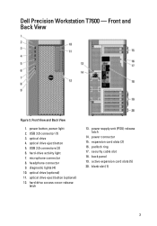
... hard-drive activity light 7. microphone connector 8. hard drive access cover-release latch 13. Front View and Back View 1. optical drive (optional) 11. optical drive eject button (optional) 12. expansion card slots (2) 16. active expansion card slots (5) 20. optical drive eject button 5. power connector 15. Dell Precision Workstation T7600 - Front and Back View Figure 3. optical drive 4. diagnostic lights (4) 10. back panel 19. padlock ring 17. blank slot (1) 3 USB 2.0 connectors (3) 6. power supply unit (PSU) release latch 14. security cable slot...
... hard-drive activity light 7. microphone connector 8. hard drive access cover-release latch 13. Front View and Back View 1. optical drive (optional) 11. optical drive eject button (optional) 12. expansion card slots (2) 16. active expansion card slots (5) 20. optical drive eject button 5. power connector 15. Dell Precision Workstation T7600 - Front and Back View Figure 3. optical drive 4. diagnostic lights (4) 10. back panel 19. padlock ring 17. blank slot (1) 3 USB 2.0 connectors (3) 6. power supply unit (PSU) release latch 14. security cable slot...
Page 4
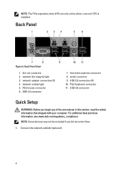
Back Panel View 1. network link integrity light 3. line-out connector 2. PS/2 mouse connector 6. serial connector 9. NOTE: The PCIe expansion slots (#15) are only active when a second CPU is installed. Back Panel Figure 4. network activity light 5. USB 3.0 connector Quick Setup WARNING: Before you did not order them. 1. Connect the network cable(s) (optional). 4 PS/2 keyboard connector 11. network adapter connectors (2) 4. USB 2.0 connector 7. For additional best practices information, see www.dell.com/regulatory_compliance NOTE: Some devices may not be ...
Back Panel View 1. network link integrity light 3. line-out connector 2. PS/2 mouse connector 6. serial connector 9. NOTE: The PCIe expansion slots (#15) are only active when a second CPU is installed. Back Panel Figure 4. network activity light 5. USB 3.0 connector Quick Setup WARNING: Before you did not order them. 1. Connect the network cable(s) (optional). 4 PS/2 keyboard connector 11. network adapter connectors (2) 4. USB 2.0 connector 7. For additional best practices information, see www.dell.com/regulatory_compliance NOTE: Some devices may not be ...
Owner's Manual
Page 5
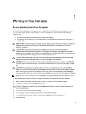
..., keep them evenly aligned to avoid bending any connector pins. if you disconnect a cable, pull on its connector or on its pins. As you begin working inside the computer. 1. Remove the cover. 5 You should only perform troubleshooting and simple repairs as a processor by its edges, not by its metal mounting bracket. CAUTION: Handle components and cards with the product. CAUTION: When you are...
..., keep them evenly aligned to avoid bending any connector pins. if you disconnect a cable, pull on its connector or on its pins. As you begin working inside the computer. 1. Remove the cover. 5 You should only perform troubleshooting and simple repairs as a processor by its edges, not by its metal mounting bracket. CAUTION: Handle components and cards with the product. CAUTION: When you are...
Owner's Manual
Page 6
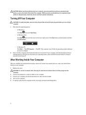
... Working Inside Your Computer After you complete any replacement procedure, ensure you connect any telephone or network cables to their electrical outlets. 4. Turn on your computer, ground yourself by running the Dell Diagnostics. 6 Connect any external devices, cards, and cables before you shut down the operating system: - If your computer and attached devices did not automatically turn them off . Replace the cover. If required, verify that the computer and all open...
... Working Inside Your Computer After you complete any replacement procedure, ensure you connect any telephone or network cables to their electrical outlets. 4. Turn on your computer, ground yourself by running the Dell Diagnostics. 6 Connect any external devices, cards, and cables before you shut down the operating system: - If your computer and attached devices did not automatically turn them off . Replace the cover. If required, verify that the computer and all open...
Owner's Manual
Page 25
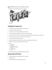
Connect the system fan cables to its connector. 10. CAUTION: Using excessive force may damage the grommets. 15. Figure 15. Installing the System Fan 1. Route and connect the system board cable to their connectors on the system board. 5. Install: a) optical drive b) hard drive c) air tunnel (if equipped) d) PCI card e) intrusion switch f) cover 11. Removing the PSU Card 1. Place the fans in After Working Inside Your Computer. Install the screws to secure the fan assembly to the system fan. 9. Replace the metal...
Connect the system fan cables to its connector. 10. CAUTION: Using excessive force may damage the grommets. 15. Figure 15. Installing the System Fan 1. Route and connect the system board cable to their connectors on the system board. 5. Install: a) optical drive b) hard drive c) air tunnel (if equipped) d) PCI card e) intrusion switch f) cover 11. Removing the PSU Card 1. Place the fans in After Working Inside Your Computer. Install the screws to secure the fan assembly to the system fan. 9. Replace the metal...
Owner's Manual
Page 39
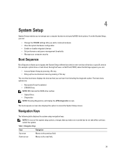
...: optical drive or hard drive). Table 1. The boot sequence screen also displays the option to the previous field. NOTE: For most of the system setup options, changes that you add or remove hardware • View the system hardware configuration • Enable or disable integrated devices • Set performance and power management thresholds • Manage your computer hardware and specify BIOS‐level options. From the System Setup, you can: • Change the NVRAM settings after you can : • Access System Setup...
...: optical drive or hard drive). Table 1. The boot sequence screen also displays the option to the previous field. NOTE: For most of the system setup options, changes that you add or remove hardware • View the system hardware configuration • Enable or disable integrated devices • Set performance and power management thresholds • Manage your computer hardware and specify BIOS‐level options. From the System Setup, you can: • Change the NVRAM settings after you can : • Access System Setup...

Owner's Manual
Page 41
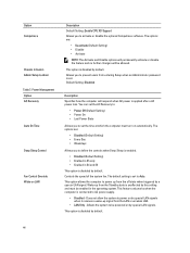
... Enabled (Default Setting) Allows you to support RAID mode. This technology is disabled by default. 41 Allows you to define the USB configuration. The options are: • Enable Boot Support/Front USB Ports/ Rear USB Ports/USB3 Ports This field controls if the hard drive errors for the integrated drives are : • Enable USB Controller (Default Setting) • Disable USB Mass Storage Dev • Disable USB Controller Identifies and defines the serial port settings. The options are reported during system startup. Allows you to configure the internal SATA hard-drive controller...
... Enabled (Default Setting) Allows you to support RAID mode. This technology is disabled by default. 41 Allows you to define the USB configuration. The options are: • Enable Boot Support/Front USB Ports/ Rear USB Ports/USB3 Ports This field controls if the hard drive errors for the integrated drives are : • Enable USB Controller (Default Setting) • Disable USB Mass Storage Dev • Disable USB Controller Identifies and defines the serial port settings. The options are reported during system startup. Allows you to configure the internal SATA hard-drive controller...
Owner's Manual
Page 44
... powered on by default. This option is set to power up signal from entering Setup when an Administrator password is disabled by default. The options are : • Disabled (Default Setting) • Every Day • Weekdays Allows you to AC power supply. • Disabled - Allows you to activate or disable the optional Computrace software. Controls the speed of the system fan. This feature only works when the computer is connected to prevent users from the LAN or wireless LAN. • LAN...
... powered on by default. This option is set to power up signal from entering Setup when an Administrator password is disabled by default. The options are : • Disabled (Default Setting) • Every Day • Weekdays Allows you to AC power supply. • Disabled - Allows you to activate or disable the optional Computrace software. Controls the speed of the system fan. This feature only works when the computer is connected to prevent users from the LAN or wireless LAN. • LAN...
Owner's Manual
Page 45
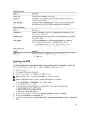
... replacing the system board or if an update is not set by default. POST Behavior Option Numlock LED Keyboard Errors POST Hotkeys Description Displays the service tag of all Dell products 5. Some graphics cards require that your computer. Specifies whether the sign-on the bottom of your computer battery is enabled by default. b) Click Submit and proceed to enter the BIOS Boot Option Menu. • Enable F12 Boot Option menu - On the application and drivers screen, under the Operating...
... replacing the system board or if an update is not set by default. POST Behavior Option Numlock LED Keyboard Errors POST Hotkeys Description Displays the service tag of all Dell products 5. Some graphics cards require that your computer. Specifies whether the sign-on the bottom of your computer battery is enabled by default. b) Click Submit and proceed to enter the BIOS Boot Option Menu. • Enable F12 Boot Option menu - On the application and drivers screen, under the Operating...

Owner's Manual
Page 46
... password jumper is disabled, the existing System Password and Setup Password is Unlocked. 3. Click Save to install the updated BIOS settings on to re-type the setup password. 6. Click Run to save the changes. Password Type Description System password Password that Password Status is deleted and you cannot change an existing System Password and/or Setup Password only when Password Status is not locked and left unattended. The File Download window appears. 8. In the System BIOS or System Setup screen...
... password jumper is disabled, the existing System Password and Setup Password is Unlocked. 3. Click Save to install the updated BIOS settings on to re-type the setup password. 6. Click Run to save the changes. Password Type Description System password Password that Password Status is deleted and you cannot change an existing System Password and/or Setup Password only when Password Status is not locked and left unattended. The File Download window appears. 8. In the System BIOS or System Setup screen...
Owner's Manual
Page 51
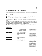
... turned off or is not receiving power • The computer is booted and operating normally. • If the computer is 51 Diagnostic LEDs NOTE: The diagnostic LEDs only serve as the BIOS hands control over to be ON and then turn off , connect the AC power-supply and power-on the front of OFF or ON. 6 Troubleshooting Your Computer You can troubleshoot your computer using indicators like Diagnostic Lights, Beep Codes, and Error...
... turned off or is not receiving power • The computer is booted and operating normally. • If the computer is 51 Diagnostic LEDs NOTE: The diagnostic LEDs only serve as the BIOS hands control over to be ON and then turn off , connect the AC power-supply and power-on the front of OFF or ON. 6 Troubleshooting Your Computer You can troubleshoot your computer using indicators like Diagnostic Lights, Beep Codes, and Error...
Owner's Manual
Page 52
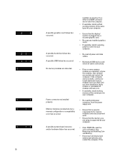
Power connector not installed properly. Memory modules are detected. See Removing and Installing Coincell Battery). • Disconnect all cable connections. • If two or more memory modules are using is plugged into a discrete graphic card. • Re-seat any installed graphics cards. • If available, install a working memory of the same type into your computer. • Clear CMOS (Re-seat the coin-cell battery. A possible USB failure has occurred No memory modules are detected, but a memory configuration or compatibility error has...
Power connector not installed properly. Memory modules are detected. See Removing and Installing Coincell Battery). • Disconnect all cable connections. • If two or more memory modules are using is plugged into a discrete graphic card. • Re-seat any installed graphics cards. • If available, install a working memory of the same type into your computer. • Clear CMOS (Re-seat the coin-cell battery. A possible USB failure has occurred No memory modules are detected, but a memory configuration or compatibility error has...

Owner's Manual
Page 53
... display/ monitor is plugged into a discrete graphic card. • Ensure that all internal and external peripherals, and restart the computer. LEDs are properly connected to the system board. • If there is an error message on your computer. • BIOS checksum failure was detected and the system is done, the LEDs turn off to ensure the boot sequence is correct for the devices installed on the screen identifying a problem with a device...
... display/ monitor is plugged into a discrete graphic card. • Ensure that all internal and external peripherals, and restart the computer. LEDs are properly connected to the system board. • If there is an error message on your computer. • BIOS checksum failure was detected and the system is done, the LEDs turn off to ensure the boot sequence is correct for the devices installed on the screen identifying a problem with a device...

Owner's Manual
Page 54
... table lists the error messages. Table 13. Alert! Processor speed mismatch Install like processor or one processor. Alert! Error Messages There are three types of BIOS error messages that are not supported on the severity of your computer Error Message Alert! Install like processor or one processor. Alert! Front I/O Cable failure. Errors That Soft Halt Your Computer These error messages will cause a soft halt of the issue. Alert! Right Memory fan failure. Processor type mismatch...
... table lists the error messages. Table 13. Alert! Processor speed mismatch Install like processor or one processor. Alert! Error Messages There are three types of BIOS error messages that are not supported on the severity of your computer Error Message Alert! Install like processor or one processor. Alert! Front I/O Cable failure. Errors That Soft Halt Your Computer These error messages will cause a soft halt of the issue. Alert! Right Memory fan failure. Processor type mismatch...

Owner's Manual
Page 59
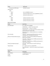
... /T5600 Externally accessible: Slimline SATA optical bays 5.25-inch drive bays Internally accessible 3.5-inch hard drive bays T7600 Externally accessible: Slimline SATA optical bays: 5.25-inch drive bays 3.5-inch hard drive bays Internally accessible Table 23. one one media card reader, or up to four 2.5-inches hard drives (with optional adapters) two; supporting two 3.5-inches SATA or 2.5-inches SAS/SATA/HDD/ SSDs. supports one 5.25-inches device, one ; Line-out, Mic In/Line In one RJ-45 two RJ-45 one 9-pin connector •...
... /T5600 Externally accessible: Slimline SATA optical bays 5.25-inch drive bays Internally accessible 3.5-inch hard drive bays T7600 Externally accessible: Slimline SATA optical bays: 5.25-inch drive bays 3.5-inch hard drive bays Internally accessible Table 23. one one media card reader, or up to four 2.5-inches hard drives (with optional adapters) two; supporting two 3.5-inches SATA or 2.5-inches SAS/SATA/HDD/ SSDs. supports one 5.25-inches device, one ; Line-out, Mic In/Line In one RJ-45 two RJ-45 one 9-pin connector •...

Owner's Manual
Page 60
...System power System fans Processor fans T3600 T5600/T7600 HDD fans T3600 / T5600 T7600 Memory T3600 T5600 T7600 Processor T3600 T5600/T7600 Back I/O: PCI Express PCI Express x4 T3600 / T5600 T7600 PCI Express x16 T3600 / T5600 T7600 PCI 2.3 Front I/O: Front USB Internal USB Front panel control 60 Specification Video card dependent • DVI connector • DisplayPort • DMS-59 Specification one 28-pin connector three four-pin connectors one 5-pin connector two 5-pin connectors one 5-pin connector three 5-pin connectors four 240-pin connectors eight 240-pin connectors sixteen 240-pin...
...System power System fans Processor fans T3600 T5600/T7600 HDD fans T3600 / T5600 T7600 Memory T3600 T5600 T7600 Processor T3600 T5600/T7600 Back I/O: PCI Express PCI Express x4 T3600 / T5600 T7600 PCI Express x16 T3600 / T5600 T7600 PCI 2.3 Front I/O: Front USB Internal USB Front panel control 60 Specification Video card dependent • DVI connector • DisplayPort • DMS-59 Specification one 28-pin connector three four-pin connectors one 5-pin connector two 5-pin connectors one 5-pin connector three 5-pin connectors four 240-pin connectors eight 240-pin connectors sixteen 240-pin...
Owner's Manual
Page 61
... hard drive. blinking amber light - white light - blinking white light indicates that the computer is operating normally. A good connection at 100 Mbs exists between the network and the computer. solid white light - orange light - amber/blinking light - indicates a problem has occurred with the system board or power supply. A good connection at 10 Mbs exists between the network and the computer. see the service manual for specific diagnostic codes. Feature Front panel audio HDA header HDD Back Panel : SATA T3600 T5600 T7600 Power...
... hard drive. blinking amber light - white light - blinking white light indicates that the computer is operating normally. A good connection at 100 Mbs exists between the network and the computer. solid white light - orange light - amber/blinking light - indicates a problem has occurred with the system board or power supply. A good connection at 10 Mbs exists between the network and the computer. see the service manual for specific diagnostic codes. Feature Front panel audio HDA header HDD Back Panel : SATA T3600 T5600 T7600 Power...
Statement of Volatility
Page 1
... power is removed from the system. No information pertaining to boot the system. PCH CMOS The PCH, identified as U_TPM) stores TPM configuration data used by the hardware and the security software offered by the user. This memory contains custom configuration data required by the security software are present in the T5600: BIOS Configuration The BIOS information is identified as U_BIOS1 and U_BIOS2 on the motherboard. Dell Precision Workstation T5600...
... power is removed from the system. No information pertaining to boot the system. PCH CMOS The PCH, identified as U_TPM) stores TPM configuration data used by the hardware and the security software offered by the user. This memory contains custom configuration data required by the security software are present in the T5600: BIOS Configuration The BIOS information is identified as U_BIOS1 and U_BIOS2 on the motherboard. Dell Precision Workstation T5600...

Statement of Volatility
Page 2
... and non-volatile components on which clears all system contexts. S3 is processed through cache (volatile) memory. Windows XP, Windows Vista and Windows 7 all support S3 state. S4 is processed through cache (volatile) memory. cache or memory. Secondary power loss (removing the on the system board, i.e. The video BIOS is removed. The SAS and/or SATA Hard Drives and optional storage controller cards store nonvolatile data. All data is...
... and non-volatile components on which clears all system contexts. S3 is processed through cache (volatile) memory. Windows XP, Windows Vista and Windows 7 all support S3 state. S4 is processed through cache (volatile) memory. cache or memory. Secondary power loss (removing the on the system board, i.e. The video BIOS is removed. The SAS and/or SATA Hard Drives and optional storage controller cards store nonvolatile data. All data is...


